by
Ralph C. Merkle
Xerox PARC
3333 Coyote Hill Road
Palo Alto, CA 94304
merkle@xerox.com
www.ralphmerkle.com
Copyright 1994 by Xerox Corporation. All Rights Reserved.
The final version of this article has been published in Nanotechnology Vol. 8, No. 2, June 1997 pages 47-52.
This is a draft. It is available on the web at http://www.zyvex.com/nanotech/6dof.html
More information about robotics is available on the web. Of particular interest is Jean-Pierre Merlet's pictorial survey of many positional devices.
Sandia has a page with further information on the use of Stewart platforms for machine tool use.
NIST has a gallery of pictures.
The Parallel Mechanisms Information Center has further information.
Robotics Online discusses Stewart platforms.
In its most basic form, the Stewart platform consists of an octahedron in which one triangular face is designated the "platform" and the opposing triangular face is designated the "base." The six struts of the octahedron that connect the base to the platform can be varied in length. The position and orientation of the platform with respect to the base will vary depending on the lengths to which the six struts are adjusted. Because there are six struts, the Stewart platform can be used to position the platform in six degrees of freedom. Although actually described earlier by (Gough, 1962) for use in tire testing, the term "Stewart platform" is more common and will be used here. Various methods of improving its range of motion have been proposed (no attempt will be made to summarize the literature in this area, a single illustrative reference is (Stoughton, 1993)). Three companies have introduced machine tools based on the Stewart platform: Ingersoll (Industry Week, 1993), Giddings & Lewis (Modic, 1994), and Hexel.
A 3-D VRML model of the Stewart platform is available on the web.
We propose a new family of positional devices which provide high stiffness and strength (like the Stewart platform) but with an increased range of motion.
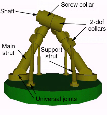
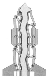
Figure 2 shows six struts attached to the base by six universal joints which each provide two degrees of freedom and allow the strut to point in any direction with respect to the base. The strut itself provides one degree of freedom, permitting the two ends of the strut to rotate with respect to each other (as would occur if it were hydraulically actuated).
Alternatively, the six struts could be attached to the base by six ball joints, providing the same three degrees of freedom.
The four support struts attach to the two main struts at what might be called "collars" that provide two degrees of freedom. The collars allow the support struts to point in any direction with respect to the main struts to which they attach. The right hand main strut attaches to the uppermost shaft by a similar collar joint which provides two degrees of freedom. The left hand main strut attaches to the shaft via a helical or screw collar. This provides two degrees of freedom, but couples rotation of the collar about the shaft to movement along the shaft. This might be done by providing the shaft with helical threads, much as a threaded bolt, and by constructing the helical collar much as one might construct a nut -- with threads inside which engage the threads on the shaft. By adjusting the pitch of these threads, the rotation of the shaft can be made either more or less sensitive to movement of the tip of the left main strut away from or towards the tip of the right main strut.
The six struts can be adjusted (by means not discussed in this paper) to any desired length within a certain range. The main struts might be extended or shortened either between the universal joint and the collar (a region we call the primary strut) or between the collar and the tip (which we call the stub). Either is possible. The tips of the two main struts can be forced to any arbitrary positions in three-space within a certain range of motion. The shaft can now be oriented in all six degrees of freedom, for it is held by a collar at one end that permits rotation (but not motion along the axis of the shaft) and by a screw collar at the other end that permits motion of the screw collar along the axis of the shaft but only when that motion is coupled with rotational motion of the shaft itself.
The range of motion of the double tripod can be understood intuitively by noting that within a wide range of motion the shaft can interact only with the main struts, and likewise that the support struts can interact only with their corresponding main struts. The support struts will not interact with each other under normal conditions of operation, i.e., if we keep the left tip and the right tip within a relatively short distance (the length of the shaft is not too long) and if we further keep the left and right tips above the ground plane. This arrangement reduces the number of strut-strut interactions that can limit motion.
The interaction between each main strut and its corresponding support struts will impose no limitations under the conditions described. The interactions between the two main struts and between each main strut and the shaft will impose only weak constraints on the range of motion. The shaft can easily be turned upside down, rightside up, oriented to the left or right, front or back, etc.
The Stewart platform has the desirable property that all six struts carry only compression or tension. The double tripod can result in bending forces being applied to the main struts. This disadvantage can be reduced by shortening the stub (i.e., the distance between the tips of the main struts and the collars that connect the supporting struts to the main struts). Reducing this distance, however, can reduce the range of motion of the double tripod as it might allow the struts in the two tripods to interact with each other. Further, the screw collar can apply an (independent) bending moment to the main strut to which it connects (though under normal conditions this should be relatively minor). Forces applied to the supporting struts can be purely compression or tension (though the illustrated collar design actually has the support struts attaching slightly off center of the main struts, which provides some improvement in the range of motion of the collar but only at the cost of slightly bending the support struts under load -- even this could be eliminated by using a different joint design).
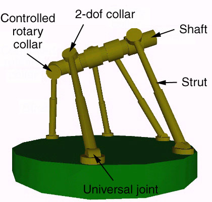
An obvious variation on this design would be to eliminate one of the support struts connected to the right main strut, and to replace the screw collar with a rotationally controlled collar. This might be called a five-thirds double tripod or just a five-thirds tripod. It would provide truly continuous rotary motion of the shaft.
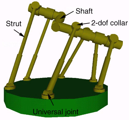
In a variation of this idea, we could use a straight shaft and replace one of the six rotary collars with a screw collar so that rotational motion of the shaft is coupled with linear motion of the screw collar along the shaft. By changing the length of the sixth strut, we could slide the screw collar along the shaft and rotate the shaft. This limits the rotational motion of the shaft around its axis, for after some distance the screw collar must reach the end of its range of motion along the shaft. By adusting the pitch of the screw, the number of rotations that the shaft can undergo can be adjusted.
Again, a VRML model is available.
In all of the devices discussed the particular arrangement of joints can be varied. The universal joints could be replaced with ball joints (which provide an additional degree of rotational freedom) eliminating the need for a rotational degree of freedom along the strut. The attachment points of the struts could be varied along the length of the shaft and on the supporting structure.
While the crank permits continuous rotation of the shaft, in other respects its range of motion is not greatly dissimilar to that of the more usual type of Stewart platform (although the range of motion can be significantly altered by adjusting the placement of the collars along the shaft).
(1) positional variance = sigma2= kBT/k
This equation, derived in (Drexler, 1992, chapter 5), relates stiffness k (in N/m) and thermal noise kBT (in J) to positional variance sigma2 (in m2) in one dimension. Sigma (= the mean displacement) is just the square root of the positional variance sigma2. To use this equation, we must know kBT and k. At room temperature, kBT is about 4 x 10-21 J. The stiffness k is related to the type and shape of the material in a complex way. We will consider simple examples where classical equations for stiffness are well known and derive approximate results which illustrate the basic issues.
The basic equation describing stiffness is:
(2) F = -k d
where F is the restoring force (in N) and d is the displacement (in m). Note that this equation is linear and assumes a perfectly elastic material (i.e., one that doesn't undergo permanent deformations when stretched). An excellent discussion of elasticity and the basic equations involved is given in (Feynman, 1964, Vol II, section 38).
(3) F = -(3 E I / L3) d = - [(3 pi r4 E) / (4 L3)] d
where:
(4) kdisplacement = ( 3 pi r4 E ) / (4 L3)
If we model a robotic arm by such a rod, then its positional variance can be derived by substituting (4) into (1) giving:
(5) ( kBT 4 L3 ) / ( 3 pi r4 E )
A more detailed analysis is given in (Drexler, 1992), but for our purposes the simpler model will suffice.
(6) kstretch = pi r2 E / L
The positional variance of a single strut in a Stewart platform is given by subsituting (6) into (1) giving:
(7) kBT L / ( pi r2 E )
If we assume that the positional variance of the Stewart platform in any given direction is approximately equal to the positional variance of a single strut, then (7) also describes the approximate positional variance for the Stewart platform.
Equating (5) and (7) (i.e., comparing a robotic arm with a Stewart platform which has the same thermally induced positional uncertainty) lets us derive the relationship between the radius of a strut in a Stewart platform and the radius of a robotic arm of similar stiffness:
(8) rstewart = rarm2 sqrt(3) / ( 2 L )
Which can also be expressed as:
(9) rstewart / rarm = ( sqrt(3) / 2 ) ( rarm / L ) = 0.87 ( rarm / L )
The smaller the value of (9), the less structural mass will be required in a Stewart platform compared with a robotic arm of similar stiffness. (9) makes it clear that the Stewart platform has the advantage when L is large and rarm is small, i.e., when the robotic arm is long and slim. As the robotic arm becomes shorter and squater the advantage of the Stewart platform is reduced.
A final caution: we have assumed that the stretching of each strut in the Stewart platform is linear. However, in compression a strut can buckle. As a consequence, we would expect that under certain conditions the assumption of a linear restoring force would break down and our equations would give incorrect answers.
The critical buckling force for a rod is (Feynman, 1964):
(10) Fbuckling = ( pi2 E I ) / L2
where I is the moment of inertia for the particular cross section. For a rod (which has a circular cross section), I = pi r4 / 4, so the critical buckling force is:
(11) Fbuckling = ( pi3 r4 E ) / ( 4 L2 )
Substituting (6) and (11) into (2) we can deduce the displacement at which the rod will just start to buckle. Shortening the rod by more than this critical length will cause deviations from linearity. The critical displacement is:
(12) dbuckling = -(pi2 r2) / (4 L)
Provided that the mean error in position is smaller than the buckling distance, our linear approximation for the response of the struts to thermal noise should be reasonable. As the mean error approaches the buckling distance, our approximation becomes increasingly suspect and our computed answer becomes increasingly distorted by the non-linear component of the restoring force.
A numerical example can provide some intuition. For:
Because the angular motion around Pattachment is zero, the torque created by Ftip and Fbase must be equal, or:
(13) Ftip Lstub = Fbase Lprimary
The line tangential to the main strut at Pattachment is a convenient reference from which to measure deflections. The stub and the primary can be viewed as two beams cantilevered from Pattachment and parallel at that point to the tangent line. The equations for these deflections (provided that theta is small) are similar to (3) and are:
(14) dbase = Fbase (4 Lprimary3) / ( 3 pi rtripod4 E )
(15) dtip = Ftip (4 Lstub3) / ( 3 pi rtripod4 E )
The angle, theta, is arc sin ( dbase / Lprimary ). For small theta, this is approximately:
(16) theta = dbase / Lprimary
The total deflection of the tip is just the sum of dtip and the angular deflection caused by theta and the distance Lstub:
(17) dtotal = dtip + Lstub sin ( theta ) = dtip + Lstub theta
Combining equations (13) through (17) gives:
(18) dtotal = Ftip ( 4 Lstub2 L ) / ( 3 pi rtripod4 E )
The stiffness of the tip with respect to deflection is therefore:
(19) ktripod = ( 3 pi rtripod4 E ) / ( 4 Lstub2 L )
and the positional variance is given by:
(20) ( kBT 4 Lstub2 L ) / ( 3 pi rtripod4 E )
This, however, neglects the contribution to positional uncertainty caused by the stretching of the support struts: this can be computed by using equation (7) with a radius equal to the radius of the support struts. (Provided Lstub is small compared with L, we can neglect the fact that the stretching of the support struts will actually be slightly magnified at the tip of the main strut by leverage). These positional variances are approximately additive, so the total positional variance of the double tripod is approximated by:
(21) ( kBT 4 Lstub2 L ) / ( 3 pi rtripod4 E ) + kBT L / ( pi rsupport2 E )
This approximation assumes that the stretching of the main strut can be neglected. When the length of the stub is long compared with the radius of the support struts, then (21) is dominated by the bending of the main strut. As the stub becomes short compared with the radius of the support struts, (21) is dominated by the stretching of the support struts.
As it is expected that the stub will normally be longer than the radius of the support struts, we can most easily determine the relationship between the radius of the main strut and the radius of a robotic arm of similar positional uncertainty by equating (20) (rather than 21) with (5) giving:
(22) rtripod = sqrt( Lstub / L ) rarm
While this will give inaccurate values when Lstub is smaller than rsupport, it is a simpler and more intuitively meaningful expression than one derived by equating (21) with (5). Designing a double tripod with Lstub smaller than rsupport is likely to be unusual. Equation (22) will also give inaccurate values when Lstub approaches L: this regime of operation is also expected to be rare.
Making Lstub almost as small as rsupport will improve stiffness while keeping the total structural mass of the double tripod at a minimum. Increasing Lstub will sacrifice some stiffness but will increase the range of motion.
A numerical example can help to make these results more intuitive. If (as before) we wish a positional variance of 10-22 meters2 and a length L of 100 nm, and if Lstub = 10 nm and Lprimary = 90 nm; then the radius of the main struts must be 3.6 nm. While not as good as the 1.1 nm radius of the struts in the Stewart platform, it is a definite improvement over the 11.4 nm radius of the robotic arm.
In summary: the double tripod shows improved stiffness when compared with conventional serial linkage manipulators (e.g., a robotic arm) and improved range of motion when compared with the Stewart platform. The tradeoff between stiffness and range of motion can be flexibly adusted by altering the positions of the attachment points of the support struts on the main strut. The closer the attachement points to the tip, the more closely the double tripod resembles a Stewart platform: its range of motion is reduced while its stiffness is increased. By moving the attachment point away from the tip (increasing the value of Lstub), we can increase the range of motion but only by decreasing the stiffness and increasing the thermal positional error.
It is worth emphasizing that the formulae in this section are approximate and are provided to illustrate trends and give an intuitive understanding of the tradeoffs involved. Specific systems are likely to differ from the results given here. A more detailed analysis would be required to determine the most advantageous approach in any specific design situation. Specific molecular systems are best analyzed using molecular mechanics and molecular dynamics.
 This
page is part of the
nanotechnology web site.
This
page is part of the
nanotechnology web site.