Ralph C. Merkle
Xerox PARC
3333 Coyote Hill Road
Palo Alto, CA 94304
merkle@xerox.com
Copyright 1990 by Xerox Corporation.
All Rights Reserved.
This article was published in Nanotechnology, Volume 4, 1993, pages 114 through 131. This version differs from the published version, and might contain some errors introduced during translation into HTML.
Nanotechnology is published by IOPP (the Institute of Physics Publishing).
This neglects any special handling that might be required for the initial and final states of the computation. The initial logical state might not have a predecessor, and the final logical state might not have a successor. Alternatively, the predecessor of the initial state might be the final state, and the successor of the final state might be the initial state (i.e., the computation could be a giant loop). These states are rare in most computations.
The laws of physics are fully reversible at the microscopic scale, and so a physical system implementing a logically irreversible system is faced with a problem: when the logically irreversible system maps two logical states onto a single result state, the physical system must somehow map two physical states onto a single result state, as well. This, of course, is impossible (for the underlying laws of physics are reversible, and hence the physical system is reversible), and so something has to give.
In today's computational systems, a single logical state will be represented not by a single physical state, but by any one of several possible physical states (which differ from each other in only trivial ways). We can rephrase this by saying that each logical state of the system is represented by a certain volume of phase space, e.g., by a certain range of possible physical states. When we perform a logically irreversible operation and merge logical states, we must either compress the representation in phase space or increase the volume of phase space that represents a logical state. If we ban indefinite growth in phase space then we are forced (at some point) to compress the phase space representation of the logical state. Phase space, however, is incompressible (which corresponds to the statement that merging two physical states is impossible, for the laws of physics are reversible). As a consequence, irreversible operations force an increase in the volume of phase space occupied by the system. However, if the allowed computational degrees of freedom in the system are not allowed to expand, then this increase in phase space must take place in the non-computational degrees of freedom, e.g., waste heat.
Because mapping two logical states onto a single output state effectively erases a bit of information, the fact that irreversible logic must dissipate heat can also be stated as: erasing information must dissipate heat. Erasing a single bit of information generates at least ln(2) x kT joules of heat.
By contrast a logically reversible system can be mapped onto the reversible physical world without the mismatch that occurs with logically irreversible systems. There is no need to compress phase space, and the mapping between logical and physical representations need not perform a basically non-physical act, e.g., the erasure of information. As a consequence, there is no fundamental need to dissipate heat during the course of a computation.
This discussion of reversible logic has been given in terms of a computing system, rather than in terms of individual logic elements. This avoids a problem which can cause confusion: one and the same logic element can be viewed as either reversible or as irreversible, depending on the system context in which it is used. For example, AND gates are often cited as "irreversible" logic devices. As commonly implemented and used, AND gates are indeed irreversible. However, it is possible to use some types of AND gates in a reversible fashion. All we need to do is insure that the operation of the AND gate takes place in a system context which does not erase information. If the two inputs to an AND gate are erased following computation of the result then we must dissipate heat. If, however, the two inputs are not erased, then we have not erased any information and the computation need not be irreversible nor fundamentally dissipative.
This is a general principle: any irreversible combinational function F can be embedded in a larger reversible function F'. We might define F' as: F'(x) = <x,F(x)>. The new function F' simply computes F and then concatenate the input x onto the output, insuring that we have not erased information. We could, if convenient, retain even more information. If, during the course of computing F, we happen to compute various intermediate results i0, i1, ... in, then we could retain these intermediate results as well. We could define F" = <x, i0, i1, ... in, F(x)>. F" is also reversible, and by keeping the additional information its implementation might be simplified.
As a consequence it is possible (in the proper context) to use AND and OR operations in a reversible computation. The physical instantiation of such a logical computation can be done in a way which preserves local reversibility and is asymptotically nondissipative. Later in this paper we will sometimes compute irreversible functions F in a manner which is logically and thermodynamically reversible. The actual implementation is done by retaining the intermediate values of the computation, as well as the input. This insures logical reversibility. In actual fact, the computation of F has been embedded in the computation of F", where F" is logically reversible.
In summary, reversible computations are consistent with the basic laws of physics at a microscopic scale, while irreversible computations are in some sense fundamentally incompatible. The price we must pay for this incompatibility is heat. If we don't want to pay the price then we must learn to compute in harmony with the natural laws of physics, e.g., we must learn how to design reversible computers.
A more recent reason for interest in mechanical logic has been that several proposals for reversible computation were basically mechanical in nature[11]. Two mechanical designs that are well known in the reversible logic community are Fredkins "billiard ball" model of computation[7] and Bennett's "Brownian Clockwork Turing Machine"[3, 8]. Drexler's "rod logic" also implements combinational logic in a reversible manner[2]. In the billiard ball model, billiard balls are fired into the computer and their ballistic trajectory -- they bounce off each other and off fixed "mirrors" - defines an arbitrary reversible computation. This is an example of a computation which dissipates as little energy as desired while rapidly computing an answer.
In the clockwork Turing machine, the state of the computation can "drift" either forwards or backwards, subject to a small "driving force." The energy dissipation can be made arbitrarily small by making the driving force smaller and smaller, though at the cost of reducing the computational speed.
More recently there has been interest in mechanical logic devices because (a) it should be possible to scale them to the molecular size range, (b) at such sizes the speed of operation becomes reasonable (sub nanosecond switching times) and (c) analyzing molecular mechanical logic devices is relatively simple (an important point when the devices can't yet be built)[2, 18]. Further, it should be possible to make molecular mechanical devices that are much smaller than molecular electronic devices (though the ultimate speed of operation of molecular mechanical devices will almost certainly be slower than that of molecular electronic devices).
To gain some perspective on this consider that an "AND" gate which has a power supply of one volt and which allows a single electron to go from that one volt supply to ground during the course of a switching operation, will dissipate one electron volt. Although one electron volt is about forty times kT (and well above the theoretical limit), it will be difficult for simple improvements of current devices to reach even this level of energy dissipation. Extrapolating present trends, we should reach forty kT between the year 2000 and 2010, e.g., within ten to twenty years.
As a consequence, we can state quite confidently that one of three things will occur: (a) the historic rate of decreasing energy dissipation per device operation will slow or halt in the next one or two decades or (b) we will operate computers at lower temperatures or (c) we will develop new, novel, reversible computer systems that can beat the kT barrier.
The first option is quite unattractive. The heroic cooling methods used in the Cray 3 supercomputer to remove the heat generated by the computer's operation suggest that failure to reduce energy dissipation per gate operation would be a major limiting factor in future computer performance. Further, although the raw cost of electrical power is not yet a major limitation, it would become so in the future if reductions in energy dissipation did not keep pace with advances in other areas. The Wall Street Journal[37] said "Computer systems currently account for 5% of commercial electricity use in the U.S., with the potential to grow to 10% by the year 2000."
The second option will not reduce overall energy dissipation. If we operated future devices at 3 Kelvin we could reduce energy dissipation by a factor of 100 - but for fundamental thermodynamic reasons the coefficient of performance of the refrigerator for the system can be at best 3K/(300K - 3K ~ 0.01[20]. Thus, the lower energy required per gate operation will be balanced by the increased energy needed by the refrigerator. Further, in many applications low temperature operation is not an option. The use of liquid nitrogen in laptop computers or many embedded applications is not attractive. However, factors other than net energy savings can make low temperature operation worthwhile. Some potentially attractive devices don't operate at higher temperatures: they have to be refrigerated or they don't work. A large mainframe computer made from such devices and operated at a low temperature might be the most economical method of delivering computational power in some cases. Refrigeration per se, however, does not seem too attractive.
Finally, and most attractively, we could develop reversible logic devices. Such devices would, in theory, allow energy dissipations indefinitely below kT per logic operation. While some barrier will likely eventually be encountered, the use of reversible logic should allow us to continue current trends in energy dissipation per logic operation for the longest possible time. Further research in this area is the most appropriate response to the rather limited range of possibilities that face us.
We can go one step further without making any changes in computer architecture: the simple register-register add instruction R1 = R1 + R2 is logically reversible. With proper hardware, this particular instruction could in principle be made to dissipate as little energy as we desired. While irreversible instructions (e.g., R1 = 0) would still dissipate greater energy, the overall energy dissipation of the computer could be reduced significantly if a reversible system were developed and used to implement the reversible instructions. Of course, once the energy-wasting irreversible instructions were identified, compilers would learn to avoid using them. This would provide an entirely evolutionary path from the current irreversible designs to computer architectures that were as reversible as was practically feasible. While there is debate about how far this trend can go it is clear that a significant percentage of computer operations can be made reversible - perhaps a remarkably high percentage.
An early electronic proposal by Likharev based on Josephson junctions[9, 10] "...is particularly significant, because it is a genuine example ... of a system that has frictional forces proportional to velocity" according to Landauer[6]. Likharev's "parametric quantron" is directly analogous to the second proposal made later in this paper. The parametric quantron is based on Josephson junctions and operates at low temperatures. Modern "high temperature" superconductors should allow operation at liquid nitrogen temperatures (although Josephson junctions have not yet been demonstrated to work at that temperature), but the low temperature of operation is still a significant disadvantage. The parametric quantron uses magnetic fields to transmit logic information from device to device. It cannot be scaled to the size range considered here for molecular mechanical devices, and the speed-power trade-off in the parametric quantron might not be significantly better than the speed-power trade-off in molecular mechanical devices.
The first proposal discussed here is derived from the work of Drexler[2], who has argued persuasively that mechanical logic devices can be scaled to the molecular level. The scaling properties of current electronic devices are unlikely to be as good. Drexler's proposed "rod logic" is also reversible. Drexler concluded that rod logic, when scaled to molecular size, should eventually be able to achieve an energy dissipation of somewhat less than kT at 300 Kelvins with gate delay times of 50 picoseconds. Reducing the speed of operation would further reduce energy dissipation. Drexler, however, also argues that electronic devices will very likely prove superior in speed of operation, a conclusion supported by recent work by Merkle and Drexler[40].
The primary reason for pessimism about the speed of mechanical logic is that the nuclei of atoms have greater mass than electrons, and so any device which depends on movement of the nuclei seems doomed to be slower than a device that uses the motions of electrons. The carbon nucleus is over 20,000 times as massive as an electron, and will normally accelerate roughly 20,000 times more slowly. An alternative view is that the speed of sound in solids is roughly 104 meters per second, whereas the speed of electronic signals is roughly 108 meters per second.
Speed is not the only important criterion for evaluating logic devices. If small size is the deciding criterion then molecular mechanical reversible logic is more attractive. Small size might make it competitive for some applications (high density memory, for example) where speed is not paramount. While the greater mass of nuclei as compared with electrons results in slower speed, it also greatly reduces the distance through which the nuclei can tunnel. One of the major limitations in scaling electronic devices to the smallest possible size is the ability of electrons to tunnel distances of a few nanometers. By contrast, devices whose function depends on the position of nuclei can be scaled to linear dimensions of two nanometers or less[2]. It might be that an electronic device only two nanometers across will be forever infeasible because a single electron can tunnel this distance (though such a claim must be viewed with caution). Thus, molecular mechanical devices might enjoy a fundamental advantage in terms of small size.
Another limitation of mechanical devices is the sliding motion of one surface upon another. This is not a significant problem if atomically perfect surfaces can be used as Drexler assumes[2, 18, 19], but current manufacturing techniques are not able to achieve this level of perfection. Drexler[12, 18] and others[13, 14] have argued that we will eventually be able to build most physically realizable structures, including complex molecular logic elements which are atomically precise. While electromechanical logic devices employing sliding silicon parts have been built and are radiation resistant[4], the friction and wear caused when imperfect silicon surfaces slide over each other is a major drawback.
As we will demonstrate, a mechanical logic device need not involve a sliding motion of one surface past another. Elimination of the sliding motion results in several advantages. First, it simplifies the analysis of molecular-scale mechanical logic devices. Because such devices cannot be built with current technology, any claims about their performance must rest on theoretical analysis. By eliminating the sliding motion the analysis becomes simpler and more fool proof.
A second more practical advantage is the elimination of the sliding motion when larger devices are built with current technology. The use of non-sliding logic in silicon eliminates the wear and friction that the sliding action creates. The energy dissipation of the device can therefore be substantially reduced, and the operational lifetime extended.
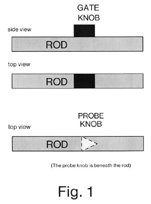
The rods must be constrained in their motions so that they cannot move except along the specified axis, nor rotate and change the location of the knob. Either of these illegal motions would let one rod slip past the other and cause a logic failure.
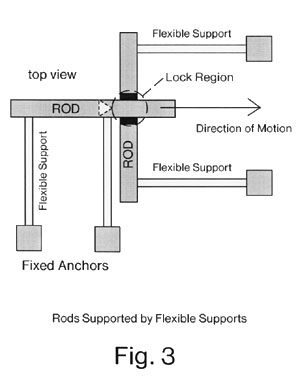
Drexler constrained the rods by embedding them in a "matrix," a solid block of material with "channels" in which the rods are obliged to slide. We eliminate the matrix by the simple expedient of mounting the rods on flexible supports, which hold the rods in position (see Figure 3). When a rod is pulled, the supports are elastically deformed (which allows rod motion). If the supports prevent lateral motion of the second rod then the collision of the probe knob with the gate knob will block the further motion of the probe knob. If the supports do not sufficiently prevent lateral motion of the second rod during the collision, then a fixed "lock support" can be placed behind the lock to prevent the gate knob from being pushed out of position by the force of the probe knob. The probe knob would then force the gate knob against the lock support, and the further motion of the probe knob would be prevented.
The elastic supports are illustrated only in figure 3. For the sake of clarity, further illustrations of non-sliding logic will not show the elastic supports. However, the reader should presume that each rod is held in position by an appropriate set of supports, even though they are not shown.
The length of the rods must also be controlled. Stretching of the rods would change the positions of the gate knobs. Should the gate knobs move a sufficient distance from their correct location from this cause, even though they continued to move only in the channel, the probe knobs would slip past them. While stretching is usually insignificant at the macroscopic scale, it is significant and must be taken into account on the molecular scale. Drexler reduced this source of error by applying tension to the ends of the rods. When this is done the material from which the "rods" are made can be both flexible and compressible, and might be better described as string. The term "rod" should thus be viewed with some caution, as many rather un-rod-like structures can be used quite effectively.
Rod logic is somewhat different from many popular logic systems. In most current systems, the output signal from a typical gate is available shortly after the input signals are applied. This does not occur in rod logic, which is fundamentally a clocked system. Rods do not move unless pulled, and only when a rod is pulled can we tell if it is blocked or unblocked. The output signal is not available until after the input signals are applied and the output rod is pulled. For this reason, the temporal pattern used to pull the rods (the clocking sequence) is of critical importance in the operation of a rod-logic circuit. At each point in time a given rod can be (a) pulled or (b) released or (c) left unchanged. If it is pulled, it either moves or does not move, depending on whether or not the locks associated with the rod are blocked or unblocked. Because the rod might or might not move when it is pulled, it is convenient to put a spring between the rod and the source of the motion used to pull the rod. This spring is called the "drive spring." The source of motion is called the "driver." If the rod does not move when the driver moves, then the drive spring extends. Although we refer to "releasing" the rod, a better description might be "unpulling" the rod. The force applied to the rod should be gradually relaxed and the rod gradually allowed to resume its original position to minimize energy dissipation.
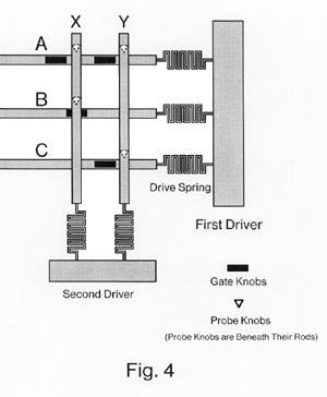
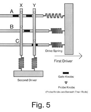
We now give an example of a complete cycle of operation for a simple logic function (see Figure 4). Three inputs, A, B, and C, enter from the left along the three horizontal rods. The first driver is on the right, and three drive springs connect rods A, B, and C to the driver. Two outputs, X and Y, exit downwards along the two vertical rods. Two drive springs connect the bottoms of the rod to the top of the second driver. At the intersection of each horizontal rod with each vertical rod, there can be a lock. Note that each lock can initially be either blocked (occupied by the gate knob) or unblocked (not occupied by the gate knob).
The cycle of operations proceeds as follows. First, the first driver moves to the right. This applies force to the three rods A, B, and C through the three drive springs. Rods B and C are free to move, while rod A is blocked (by a lock not shown on the diagram). The drive spring for rod A extends, while the drive springs for rods B and C do not. The motion of rods B and C unblocks the gate at the intersection of B and X, but blocks the gate at the intersection of C and Y. The two locks controlled by rod A continue to be unblocked. This is illustrated in Figure 5. Second, the second driver moves downwards. This applies force to the two output rods X and Y. X is free to move, and does so, while Y is blocked. The drive spring for Y extends. This is illustrated in Figure 7. Third, the second driver is released and rods X and Y resume their original positions. Fourth, the first driver is released and rods A, B and C resume their original positions.
Note that cycles 1 and 2 compute an output, while cycles 3 and 4 reverse the motions involved in cycles 1 and 2, thereby "uncomputing" the output. Therefore this clocked sequence of actions is entirely reversible. The energy dissipation per operation could, in principle, be made less than kT. If we attempted to change this sequence, e.g., we interchanged cycles 3 and 4 and released driver 1 before releasing driver 2, then the probe knob and gate knob would slide past each other at the lock at the intersection of C and Y. That is, the wrong sequence of clock signals would introduce sliding motion. The clock sequence in rod logic must be carefully specified to prevent this kind of problem.
In general, if we have an N level logic circuit, then we will need to divide the rods into N groups numbered from 1 to N. Each rod in a group will be connected to the corresponding driver. The drivers will be moved in sequence, starting with driver 1 and terminating with driver N. The rods in group i will control the motion of the rods in group i+1. After the Nth level rods have been pulled, the drivers will be released in reverse sequence, starting with driver N and terminating with driver 1.
What has been described so far will allow the construction of an N level reversible combinational logic circuit. To be useful, we must also specify a latch which can store the output of the combinational circuit. This can be done relatively easily by modifying the basic rod logic design described so far. We define a set of "latch rods" which, in essence, are the N+1st logic level rods. For pedagogical purposes we will refer to the Nth level rods as either "Nth level rods" or "output rods," whichever seems clearer. In essence, the latch rods are used to "latch up" or remember the state of the output rods. The proper latch rods will be moved when the output rods move. The latch rods will then be locked into position. This arrangement is described in more detail in the next few paragraphs.
Each output rod will be lengthened and a new "drive knob" will be added near the end away from the drive spring. A "drive knob" is a knob whose purpose is to pull a "driven knob," and in consequence to move the rod to which the driven knob is attached, also called the "driven rod." The driven rod, like all rods, will move along its axis. As a consequence, the driver rod and the driven rod must be parallel, for the motion of the drive rod will be transferred directly to the driven rod. The action of the driver knob is unlike the action of either a "probe knob," which is used to determine whether or not a lock is blocked, or a "gate knob," which is used to block and unblock a lock. The drive knob on the output rod will be used to pull on the driven knob which is attached to the latch rod. In this case, the output rod is the driver rod and the latch rod is the driven rod. The latch rod is parallel to the output rod, not at right angles. If the output rod is pulled and moves, then the driver knob on the output rod will pull on the driven knob on the latch rod, and the latch rod will also be pulled. Because the latch rod will not be blocked, it will also move. (See figure 8).
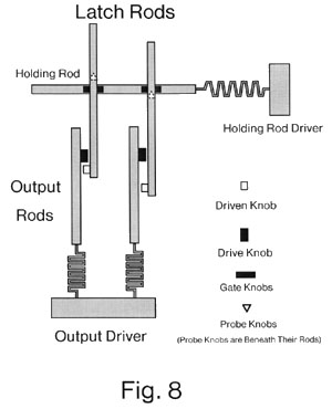
Once the latch rods have been moved into their proper positions, they are held in place by the "holding rod." The holding rod is at right angles to the latch rods, and is always free to move. The holding rod has gate knobs at all positions. All the locks between the latch rods and the holding rod are initially unblocked. After the latch rods are in their correct position, the holding rod moves and all the gate knobs on the holding rod block all the gates. In those latch rods which have not moved, the probe knob on the latch rod is clear of the lock and has not moved through it. On those latch rods which have moved, the probe knob has been moved through the lock and is also clear of it. Thus, in either case, the holding rod is free to move and the gate knobs on the holding rod can occupy all the corresponding locks. Once the locks are blocked, the output driver is released. The output rods move back to their original positions. Those latch rods that were moved are now held in place by the gate knobs on the holding rod and cannot return to their original positions. The output rods are free to move at this point in the cycle, whether or not the latch rods have been blocked, because the motion of the driver knobs on the output rods is now away from the driven knobs. (See figure 8).
Although this method will correctly latch up the output, it now presents the problem of releasing the holding rod driver and restoring the holding rod to its original position. If we simply release the holding rod driver, then the probe knobs on the latch rods which bear upon the gate knobs on the holding rod will cause friction when the holding rod moves. This will work, but will result in greater energy dissipation both because of the friction between the probe knobs and gate knobs and because the energy stored in the latch rod supports will be dissipated when the latch rods spring free. The latch rod supports are, in effect, springs that attempt to restore the latch rod to its "normal" position. When the latch rod probe knobs are unblocked as the holding rod gate knobs move out of the locks, the latch rod will snap back to this position and oscillate, thus dissipating energy. This is in keeping with the irreversible nature of the operation: the information held in the latch rods will be destroyed, which requires dissipation of about kT per latch rod.
A more clever method would be to "unwrite" the information held in the latch rods. This differs fundamentally from erasing the information. In this technique, the information held in the latch rods is recomputed (by any method we might find convenient) and the output rods are driven with this freshly recomputed information. This recomputed information is identical to the actual contents of the latch. In this way, the pressure on the holding rod gate knobs will be released, and the holding rod will again be free to move. The holding rod driver can then be released, and the output driver (and all preceding drivers) can be released as usual. The information in the latch rods is "unwritten" in a reversible manner (no step in the unwriting process destroys information) and the energy dissipated per latch rod operation can in principle be less than kT during this process.
This allows us to remember the value computed by a combinational logic circuit in a set of latches. With some additional mechanism, we can compute an iterated reversible computation. This will allow us to perform the more or less normal sequence of operations in a computer. That is, the state of a computation in a normal CPU is held in a series of latches (flip-flops) and that state is used as the input to a combinational logic circuit which computes the next state. The next state is then clocked into the flip-flops while the previous state is destroyed. This sequence allows a conventional computer to execute a series of instructions by repeatedly computing the next state from the current state, and repeatedly replacing the current state with the next state. Of course, in a reversible computation, we not only need to compute the next state from the current state, we must also be able to uniquely determine the current state from the next state, e.g., the computation must be reversible. There are many ways of designing such a reversible computer[7, 8, 11, 15]. In the following paragraphs we describe a simple architecture for carrying out a reversible computation.
We assume that we have a reversible combinational function whose iteration we feel is computationally useful (e.g., the function implements a single instruction or step of a reversible computation). We shall call this function F. We start with the initial state of the computation stored in a set of initial latch rods which are held in position by a driven holding rod. We then compute F(initial latch rods), and store the result in a set of output latch rods, which are assumed to be initially empty.
Having once computed the next state and stored it in the output latch rods, we must unwrite the initial latch rods. To do this, we compute F-1(output latch rods), which should be identical to the state already stored in the initial latch rods. Thus, not only do we have combinational logic for computing F, we have combinational logic for computing F-1. This additional logic is absolutely necessary. If we did not have a method of computing F-1, we would not be able to re-compute the contents of the input latches. If we could not re-compute the contents of the input latches, we could not unwrite them (which can be done in an asymptotically non-dissipative fashion) but would instead be forced to erase the input latches (which is an inherently dissipative operation). Only after we have unwritten the input latches can we reversibly transfer the contents of the output latches to the input latches. Once this final transfer has been done, we are ready to perform another cycle in the computation of F.
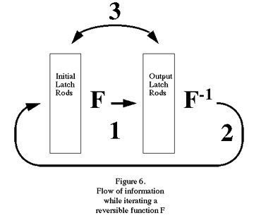
The summary of one full cycle of computation is illustrated in figure 6. In step 1, we compute output latch rods = F(initial latch rods). The output latch rods are left holding the output, while we uncompute the intermediate stages in the computation of F. This leaves the input in the initial latch rods, and the output in the output latch rods. In step 2 we compute F-1(output latch rods) and use this information to unwrite the initial latch rods. After unwriting the initial latch rods they hold 0. We then uncompute the intermediate stages in the computation of F-1(output latch rods). This leaves us in a state in which the output latch rods hold the next stage of the computation, while the input latch rods hold 0. In step 3 we exchange the contents of the output latch rods and the input latch rods. This exchange is actually done in two steps: first, we write the initial latch rods using the output latch rods as the source of information. This operation can be done reversibly because we know the initial latch rods hold 0. Second, we unwrite the output latch rods using the initial latch rods as the source of information for the unwriting operation.
After completion of these operations, we are right back where we started except that the initial latch rods hold F(contents of initial latch rods from start of previous cycle). All operations were done reversibly, and so can be carried out in an asymptotically nondissipative fashion.
In general, the parts in a molecular mechanical system will be held in place by some restoring force. This restoring force will act like a spring and will tend to prevent the part from moving away from its assigned position. If the restoring force is linear in the displacement (which is often a good approximation) then we have:
f = ksx
where ks is the spring constant, x is the displacement, and f is the restoring force. It requires a certain amount of energy to displace the part, so we also have:
E(x)= ksx2/2
where E(x) is the energy of the system when the part is displaced by a distance x. In thermal equilibrium the probability of being displaced by an amount x falls off exponentially as the energy E(x) increases. The probability of being in error falls off even more rapidly in the displacement[18]:
P(x) = sqrt(ks/2 pi kT) exp( (-x2ks)/(2 kT) )
where P(x) is the probability of being displaced by a distance x from the correct position.
The spring constant for a single carbon-carbon bond is approximately 440 newtons/meter[18]. At room temperature a spring constant of this value implies that a displacement of 0.05 nanometers has a probability of about 10-47. Even for a spring constant of 1 newton/meter, the probability of being displaced by a nanometer is about 10-43. Molecular mechanical systems designed to tolerate positional errors on the order of several tenths of a nanometer can have very high reliability in the face of thermal noise at room temperature.
Appropriate selection of materials and speed of operation can be used to minimize the energy loss during surface-surface contacts. Drexler showed that energy losses from this source can be quite small (less than kT) even when switching speeds are 50 picoseconds[2].
As an aside, even sliding motion need not cause problems. Provided that two sliding surfaces are structurally stable (so that the formation and breaking of chemical bonds is not an issue), the surface-surface interaction in this case will also be described by a potential energy function. In the case of two surfaces that are constrained to move past each other in one dimension, the potential energy function is a simple function of a single variable. If the two surfaces are periodic (the atoms on the surfaces are regularly spaced) and if the periods for the two surfaces are the same (the two surfaces are made of the same material) then the potential energy as a function of position will have high peaks and low valleys: the two surfaces will resist sliding past one another. If, however, the two surfaces are selected to have different periodicities (they are made of different materials, or the surfaces are skewed with respect to each other along the line of motion) then the potential energy as a function of position can be essentially flat[18, 19, 39]. In this case, there will be little resistance to motion. If the motion of one surface past another is relatively slow then energy dissipation can be quite small[2, 18]. Thus, while sliding motion introduces an additional design problem, it is a problem that can be overcome if the surfaces can be built to atomic specifications.
To illustrate the principle underlying this kind of logic, consider the behavior of an isolated elastic vertical beam when a compressive force is applied from the top. Imagine, for example, that you hold a business card vertically in your hand by its edges, forefinger on top and thumb on the bottom. When you squeeze the card it will buckle in either of two directions. If the card was initially straight, then the direction of buckling will be very sensitive to any lateral force applied to the middle of the card. If you push gently to the left on the middle of the card and then squeeze it, it will buckle to the left. If you push gently to the right and then squeeze, it will buckle to the right. Once the card has begun to buckle in one direction it is difficult to force it in the other direction. In short, a small lateral force applied to the card as an "input signal" can control the direction of the large lateral displacement produced as an "output signal" when the card is buckled by a force applied from the top as a "clock signal" (see figure 9).
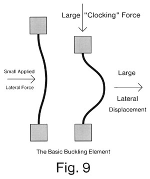
This buckling arrangement can be used to define logic operations. If one or more input forces are applied laterally to the midsection of the card, then the midsection will be pushed either somewhat to the left or somewhat to the right, depending on the sum of the applied forces. When the large clocking force is applied, the initial direction of deformation will be continued, and with greater force. This can be viewed as a threshold device, for the output state is controlled by the sum of the input forces. Once buckled in one direction or the other, the card will remain in that state and will be resistant to a change to the other stable state (in which it is buckled in the other direction). Thus, the device can also be viewed as a "flip-flop" or memory element, as well as a threshold device.
This provides a simple mechanical example of a device which, under clock control, can be shifted from a monostable state to a bistable state and back again (e.g., buckled and unbuckled). Likharev's "parametric quantron" [9, 10] provides an electronic method of doing the same thing. The lateral force applied to the card is analogous to the external magnetic flux phie in the parametric quantron, the buckling force (or clock force) is analogous to the control current Ic which controls the critical current IM of the Josephson junction, and the lateral position of the card is analogous to the net magnetic flux phi in the ring. Likharev said "In fact, the only role of the parametric quantron in our discussion has been to demonstrate how a flexible bistable potential well could be physically realized"[9]. The mechanical implementation given here is another way of making such a flexible bistable potential well which provides a simpler and more accessible illustration of the basic principles.
Landauer[26] has previously proposed the use of a bistable spring as an element in a transmission line, and suggested that such a bistable spring could be implemented using a buckled metal plate or card. This proposal was made in the context of signal transmission, rather than computation, and did not consider the need to modulate the spring (e.g., buckle and unbuckle it) for the purpose of computation. The more general discussion by Landauer[27] of reversible computation using "time modulated potential wells" suggests that the wells could be implemented by the motions of charged particles. The use of buckling cards to implement flexible bistable potential wells and thereby create a reversible mechanical logic system which eliminates surface contact between the parts of the system has not previously been considered.
The use of bistable mechanical elements for memory has been proposed by Halg[35]. "It essentially consists of a surface-micromachined bridge which is longitudinally stressed so that it buckles and becomes mechanically bistable. This bistable bridge performs the memory functions." Their proposal did not go beyond memory, nor consider the concept of buckling and unbuckling the mechanical element to provide a flexible bistable potential well. The "read" and "write" operations involved a dissipative "snapping" of the buckled element from one stable state to the other stable state.
Notationally, the term "well" will be used to refer generically to any flexible potential well which can be shifted from the monostable to the bistable state and back again in a controlled fashion. In the context of the current paper, "well" usually refers to a mechanical well. Whether we are discussing a generic well or a mechanical well should be clear from context. We will use the phrase "squeeze a well" or "clock a well" to indicate that the well is shifted from its monostable state to its bistable state. The shift from the bistable to the monostable state will be called "releasing" or "unclocking."
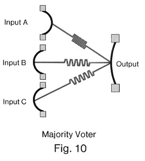
Some methods for using wells to build reversible logic have been discussed by Landauer[6, 27], who described the use of a three-input one-output "voter" circuit. A mechanical implementation of such a device is shown in figure 10. The three "input" wells are coupled to the "output" well by springs. The springs connect the midsections of the cards in the wells. The springs are bidirectional, and so the distinction between an "input" well and an "output" well is based on which wells have been clocked and which wells have yet to be clocked. Wells that have already been clocked are "inputs," while wells that are about to be clocked are "outputs." The three input wells have already been clocked, and the output "voter" well is about to be clocked. Given that all three springs have the same spring constant and have been moved the same distance by the input wells, but that the direction of motion is either to the right or to the left depending on the state of the input wells, then the actual force applied to the midsection of the card of the output well can be approximated by one of the following simple sums: -3, -1, +1, or +3. The card will move to the left if either 2 or 3 of the input cards have buckled to the left, and will move to the right if either 2 or 3 of the input cards have buckled to the right. The input wells are said to "drive" the output wells either left or right through the springs, while the output well is driven either left or right by the springs. "AND" and "OR" gates can be implemented from such voters by leaving one input fixed at logical 0 or 1, respectively.
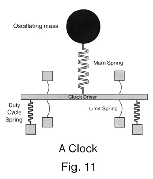
Landauer presumed the absence of a negation operation and so proposed the use of "two rail" logic in which a variable and its complement are available at all times. Negation is then accomplished by exchanging the two variables. It is relatively simple, however, to make a mechanical inverter (see figure 12) and so the current mechanical proposal can be more conventional in this respect. The ability to use an inverter can be thought of as allowing "springs" with a spring constant of -1. More generally, springs with relatively arbitrary strengths can be used. Presumably, the details of the particular implementation will limit the range of values for the spring constants in any given system.
The next step is to implement combinational logic using wells. We might, for example, assume that there are N "clock signals" applied to N sets of wells. We assume that the first set of wells has already been clocked, and holds the correct "initial state." The second set of wells, which are driven by the first set of wells, would then be clocked. The state of the computation would then be encoded in the buckled cards in the first and second set of wells. The clock for the third set of wells would be applied. The second set of wells would drive the third set of wells, and determine the direction in which the cards in the third set of wells would be driven. This would continue until the Nth clock signal was applied to the Nth set of wells. At this point, the output of the Nth set of wells would be available for use. Once the outputs from the circuit had been used (possibly in a dissipative non-reversible fashion) the clock signals could be removed in the reverse order in which they had been applied. In this way, any arbitrary function F(input wells) can be computed and then uncomputed.
Note that this sequence of operations, regardless of the nature of the combinational function F computed, is fully reversible (excluding the possibly non-reversible use of the actual output following application of the Nth clock). That is, we could compute the value of a non-reversible combinational function F, and then un- compute it in a reversible manner. In essence, we can do this because intermediate values in the computation are stored in the intermediate logic levels. In some sense, the actual "output" is really the state of all the wells in the system, not simply the state of the output wells. Although we're only interested in the state of the output wells and don't care about the state of the other wells, they are available. In the process of reversing the computation, we use the information stored in the wells in all the logic levels, not just the information stored in the output wells. Put another way, we have embedded the (possibly) irreversible combinational function F(x) into a fully reversible function F', where the output of F' includes F(x), x, and all intermediate values used to compute F(x) from x.
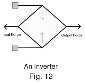
We will require N "clock signals" to compress the corresponding wells in the proper phase relationship. The simplest way to provide periodic compressive motion is to use oscillators each made from a mass and a spring. The spring of each oscillator would be connected to a clock driver. The clock driver would simply be a rigid body connected to all the wells associated with the oscillator. The mass would move up and down, compressing and uncompressing the spring. The spring, when compressed, would push the driver down upon the wells, clocking and unclocking them.
Unfortunately, such a simple oscillator suffers from two defects. First, the range of motion through which the clock driver moves might exceed what we desire. Second, the duty cycle might not be what we desire.
In order to achieve good control over the onset and removal of the clocking force, we add some additional components. In particular, we add "limit springs" both above and below the clock driver (see figure 11). These springs are highly non-linear. When they are pulled and achieve a large extension they flatten out, sharply increasing the force that they apply. Completely straightening the limit springs would require an extremely large force. This non- linearity can be used to limit the motion of the clock driver to the desired range, e.g., the clock driver will neither crush the cards nor rip off their tops during its normal cycle of operations. Instead, any excess force is taken up by the limit springs. The limit springs have a significantly smaller spring constant than the other springs in the mechanism, and so in most cases either the upper or lower limit springs will be fully extended (e.g., the wells will normally be either "clocked" or "unclocked," and will not occupy some intermediate state). During the onset and removal of the clock signal, the strength of the limit springs will "soften" the rising and falling edges. If the limit springs had no strength (e.g., were replaced by fixed-length pieces of string) then the clock driver would tend to "snap" from one extreme of its range of motion to the other. This could result in dissipation of energy. If the spring constant of the limit springs in their linear (non-extended) range of operation were too large, then the clock driver would oscillate gently between its upper and lower limits of motion. This would mean the onset of the clock signals would be too slow: the wells at stage 3 would start to be clocked before the clock signal had been fully applied to the wells at stage 2. By selecting limit springs of appropriate strength, reasonable rise and fall times for the clock signal can be achieved.
In order to adjust the duty cycle of the oscillator (so that the wells are clocked and then unclocked for the correct periods of time) we add additional "duty cycle springs" beneath the clock driver (see figure 11). If the duty cycle springs have greater strength than the main oscillator spring, then the driver will spend most of its time in the up or "unclocked" position. If the duty cycle springs are weaker than the main oscillator spring, then the driver will spend more of its time in the down or "clocked" position. In the limit, if the duty cycle springs had infinite strength (e.g., were replaced by solid rods) then the driver would always be in the up (unclocked) position. If the duty cycle springs had no strength, the driver would spend half its time in the up (clocked) position and half its time in the down (unclocked) position. By selecting duty cycle springs with an appropriate strength, the percentage of time spent in the clocked versus unclocked position can be controlled.
These clocking mechanisms involve nothing but simple mechanical motion with no contact points. By adjusting the duty cycle and the phase relationship of the different oscillators, the proper clocking signals can be generated to drive the wells. Once started, the oscillators will tend to drift and would have to be kept in the proper phase relationship with each other. Ideally, they would be phase locked. If, for example, N clock oscillators were operating at some frequency f and small multiples of f, then we might have a single master oscillator at a frequency that is a small multiple of Nf. The clock oscillators would all be phase locked to the master oscillator, and so the proper phase relationship would be preserved. Because each clock oscillator can control an arbitrary number of wells, and because the oscillators should drift out of phase rather slowly, the energy (if any) dissipated in maintaining the proper phase relationship can be amortized over many well operations. The energy dissipation per well operation from this source can be made arbitrarily small.
If we were to erase information, we would expect to find an energy dissipation mechanism which dissipated ln(2) kT or more per bit erased. We would not be disappointed. If, for example, we were to unclock logic level 1 then it would be necessary for the input to that logic level to be identical to the actual information already stored in the logic level if we are to avoid energy dissipation. In other words, each well in logic level 1 will be driven either left or right by its input. If some particular well in logic level 1 is buckled left but is being driven to the right by its input signal, then unclocking logic level 1 will be a non-reversible operation. Once we release the clock, the well will forget its original state. Should we at this point reapply the first clock, the card would buckle to the right in response to its input and not to the left: we have forgotten the original state and hence performed an irreversible act. We must pay for this forgetfulness with energy.
The energy loss in this particular system occurs as we remove the clock signal. A well buckled to the left but driven to the right will, at some point during removal of the clock, "snap" from left to right. This "snap" will occur when thermal noise is sufficient to allow the card to overcome the shrinking energy barrier that separates the leftward position from the rightward position. It will indeed dissipate an amount of energy which is several times kT. To prevent such dissipative "snap" losses, we must never drive a buckled well in the wrong direction and unclock it. If we do, we will suffer energy losses which are several times kT. Even more strongly, if we wish to unclock a buckled well the buckled well must be driven in the correct direction during the unbuckling operation. In this discussion, we assume that a well is always driven in one direction or the other. The only time that a well would not be driven in either direction would be during the very brief transition when the direction it was being driven was changing from left to right or from right to left. Thus, all unbuckling operations will take place with the well driven either left or right.
While our objective is to design a reversible logic system in which energy dissipation can be completely avoided, we might find it convenient on occasion to erase a bit. In this case, we know that the least energy dissipation we can hope to achieve is ln(2) kT. We can approach this limit by unclocking the well when the driving force is 0, e.g., the well is driven neither left nor right. In this way there will be no "snap" as the well is unclocked. This zero driving force can be approached by connecting a well that we wish to erase (the "erasee") to an otherwise unused "erasure well." The information held in the erasee can be moved into the erasure well by clocking the erasure well. Then we can "unwrite" the erasee without dissipating energy. Of course, this still leaves the erasure well holding the information that we wish to erase. Erasing the erasure well is simplified, however, because it has only a single input (that from the erasee). After erasing the erasee, it will be applying very close to zero driving force to the erasure well. Hence, when we unclock the erasure well, the driving force on it will favor neither the left nor the right position, as desired. Therefore, in those (presumably infrequent) cases where we do decide to use an irreversible operation, it can be made to dissipate close to the minimum amount of energy possible. As mentioned in the previous paragraph, in this discussion we are focusing on reversible logic which does not erase information, and so will not consider unbuckling a well when the driving force is 0.
Given a method of computing combinational logic, we must still build a computer. Again, as with non-sliding logic, we assume that there is a reversible function F whose iteration is useful. We can use exactly the same general method as described before. We add an additional logic stage to hold the output of the Nth logic level. Again, we refer to the Nth logic level as the "output," and the N+1st level as the "latch" stage. In this case, the latch stage will be identical with all preceding stages. It is distinguished only in that each "latch" has a single input from the output stage, rather than the three inputs that are common in the earlier logic levels. In this way, the wells in the "latch" stage will be buckled in exactly the same direction as the wells in the output stage. The springs that carry force between the output stage and the latch stage will always drive the output wells in the correct direction (thus eliminating the possibility of a "snap" mechanism of energy loss). We can then safely unclock the output logic level and all preceding logic levels back to the 1st logic level - which must remain clocked until it can be "unwritten." The rest of the construction used with non-sliding logic is now used for buckling logic, and results in a device which is asymptotically nondissipative.
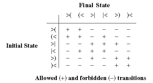
In general, the states of an individual well can be described as follows: the well is either clocked and buckled left, clocked and buckled right, or unclocked (and unbuckled). Further, the driving force applied to the card of the well can be either left or right (we ban the application of 0 force, as achieving exactly 0 force might be difficult in practice. This is certainly a pragmatic issue in many systems, but it is unclear if it is fundamental). The well can therefore be in one of six states. If buckled left, buckled right, and unbuckled are abbreviated "(", ")", and "|"; and if driven right and driven left are abbreviated ">" and "<", then the six states are: ">(", ">|", ">)", "(<", "|<", and ")<". The symbols ">(<", ">|<", and ">)<" will represent the three sets of two states in which the drive force is either left or right, e.g., ">(<" is the set of two states {">(", "(<"}. The allowed transitions are: (< to |<; |< to (<; >) to >|; >| to >); >(< to >(<; >)< to >)<; and >|< to >|<. Any transition which is not allowed is forbidden. Among the banned transitions: a card that is buckled left cannot suddenly shift to buckled right, so >(< cannot become >)<, and >)< cannot become >(<. Also, to prevent undesired energy loss, we cannot unclock a well that is buckled left but driven right, nor one that is buckled right but driven left: we ban the transitions >( to >| and )< to |<. A few other unreasonable transitions are also forbidden.
This is shown in the following table:
An unclocked well can actually transmit the drive force through itself. That is, some fraction of the drive force from the preceding well(s) can be transmitted through to the following wells. These wells will, in their turn, transmit the (now much reduced) forces on to other wells. In general, a complex web of diminishing forces will be transmitted through the unclocked wells in a system. However, if the unclocked wells have a vertical upwards force applied through their drivers, then the lateral force transmission will be substantially damped on passage through each well. Because the "legitimate" forces are significantly larger and take on only a few nominal values, small variations in the actual force applied to a particular well will not cause it to buckle the wrong way when clocked. The course of the computation is not affected by small variations or perturbations in the system. It is clear, however, that a significant figure of merit is the extent to which an unclocked well will prevent through-transmission of an applied driving force. The less force that is transmitted, the lower the "noise" forces in the system. Reduced noise will allow larger fan- in and fan-out. (Interestingly, these "noise" forces can be usefully employed in a different logic mode, described later, and the "figure of merit" would become a "figure of demerit.")
Once the clock oscillators are adjusted so that the oscillations have the correct amplitude and phase relationships, the computation will proceed. By reducing the speed of operation, the energy dissipation per well operation can be made arbitrarily small. A perfectly elastic material would exhibit no losses. Real materials approach this ideal as they move more slowly, so energy dissipation from this source can be reduced indefinitely. The method of maintaining the proper phase relationship between the oscillators might possibly require energy, but the energy dissipation per well operation (if any) from this source can be made arbitrarily small by increasing the number of wells per clock phase (only a small, finite number of clock phases are required even when the number of wells is increased indefinitely); and by increasing the stability of the oscillators so that adjustments in their frequency are infrequent. Other sources of energy dissipation (e.g., electromagnetic radiation) appear to be insignificant by comparison.
It is instructive to consider the system from the point of view of a single atom within it. The local neighborhood around the atom would change very little during each cycle: only small perturbations in the local geometry would take place. While large macroscopic motions would occur, these would never involve large changes in local structures, e.g., they would never involve the close approach of two atoms that were initially far apart, nor the separation of two atoms that were initially close. The local potential energy function describing the energy of the local arrangement of atoms as a function of the positions of their nuclei would be in a local minima. The small perturbations in position caused by the elastic deformations of the overall structure would dissipate very little energy if they were not too rapid. The energy loss that must inherently take place in such a system can be made arbitrarily small by reducing the speed of operation.
A possible candidate for a very small card would be a sheet that was one or two atoms thick. A sheet that was 10 nanometers high by 1 nanometer wide would have a few hundred atoms. We will use a very much larger size (10,000 atoms) in the calculations below simply to provide a large design margin. That is, it seems virtually certain that some arrangement of 10,000 or fewer atoms will correctly implement a card and related connecting springs. If we reduced the number of atoms available to build the device, then we would need to specify the device design in greater detail to insure that the construction was still feasible. (As an example of what should be possible in purely mechanical systems, a single "lock" in Drexler's rod logic has a volume of 4.1 cubic nanometers and somewhat fewer than 500 atoms[2]).
From a mechanical point of view, a card will become increasingly sensitive to lateral force applied to its midsection as it becomes thinner and longer. Quantitatively, we have
d= f h3/(4 E t3 w)
where f is the lateral force applied to the middle of the card, h is the height of the card, E is Young's Modulus, t is the thickness of the card, w is width of the card, and d is the distance the center of the card moves under the applied force[22]. The continuum approximation will break down as the card becomes sufficiently small and atomic structure becomes significant. In this case, molecular modeling techniques that take into account bond bending and other bond parameters would be required to analyze the behavior of the structure.
In point of fact, a card under compression is a tristable device. That is, it can buckle either to the left, to the right, or balance (perhaps precariously, depending on its thickness and height) straight up and down. As the card becomes thinner and higher, the size of the "balancing" region will become smaller and smaller. In the case of a card that was one atomic monolayer thick, this region would be vanishingly small. In a logical sense, this has no impact on the previous discussion. If we have a tristable device, then we can simply exclude one of the three stable states and utilize the remaining two stable states for device function. While this makes the "feel" of the terminology we have adopted somewhat odd ("buckled left," for example, might be implemented by a card that is balanced under compression) the principles still apply. Alternatively, by selecting the lateral force large enough to drive the physical card into either the left-most or right-most stable state (avoiding the central stable state entirely) we can (for logical purposes) ignore the existence of the central stable state. Of course, this will reduce the force sensitivity of the device (unless the card is an atomic monolayer, in which case the central stable state does not exist). On the other hand, we could get maximal lateral force sensitivity by using the central stable state and the right stable state (using only two of the three physically available stable states). A device that used only two of the three physically available states should exhibit remarkable sensitivity to lateral force. If it were properly balanced (either by being manufactured that way to begin with, or by being "trimmed" afterwards) the only limiting factor on the force sensitivity would be thermal noise. That is, the energy spent in pushing the card laterally would have to exceed several times kT, for thermal noise might otherwise cause the card's position to fluctuate enough to cause it to buckle in the wrong direction. There seems to be no other inherent lower limit on the applied lateral force.
Even though buckled logic eliminates several obvious sources of energy dissipation, dissipative mechanisms still exist. The mere fact that a real elastic system is buckled and unbuckled will cause energy dissipation in much the same way that compression and decompression of a gas causes energy dissipation[20]. Drexler concluded that the major source of energy dissipation in rod-logic operating at 50 picoseconds was from this kind of mechanism[2]. The fundamental energy dissipation mechanisms that exist even in a perfect non-conducting solid are thermoelastic damping and phonon damping[18, 32].
An infinitely slow isothermal cycle of compression and decompression of a gas can be dissipation free. In the same way, the isothermal buckling and unbuckling of a card can also be dissipation free. In reality, of course, neither operation is infinitely slow nor perfectly isothermal. If a single cycle takes time t, then the energy dissipated per cycle will be delta E = k/t for some suitable constant k. By slowing down the cycle time, the energy dissipation per cycle can be reduced indefinitely.
It is interesting to note that a relatively rigid structure of small size can only support vibrations above a certain frequency. If the speed of sound in the structure is 10,000 meters per second while the size is 10 nanometers, then the lowest frequency vibrations will be about 1012 hertz. Quantum theory dictates that the allowed vibrational modes are quantized at the frequencies (n+1/2) h f, where f is the lowest frequency vibrational mode, n is the quantum number and h is Planck's constant or 6.6 x 10⁻³⁴ joule seconds[21]. Thus, the vibrational energies are separated by h f or about 6.6 x 10⁻²² joules. This corresponds to a temperature of 6.6 x 10⁻²²/1.38 x 10- 23 or almost 50 kelvins. The average value of n at thermal equilibrium, <n>, is given by:
<n> = 1/(eh f / kT - 1)
At 50 kelvins <n> is about 0.6. At 2 kelvins, <n> is about 10-11, so the probability that n equals 0 is almost 1 (e.g., the system is almost certainly in the ground state).
To rephrase this in words, at some sufficiently low temperature a small rigid structure has essentially zero heat capacity because the transition from the ground state to the lowest excited state will require significantly more energy than can be provided by thermal noise. This in turn implies that buckling and unbuckling (e.g., mechanical distortions of the structure) will not cause any heat flow. This raises the interesting possibility that operation of a mechanical logic device below a certain temperature can result in an exponential decrease in energy dissipation as a function of decreasing temperature. A logic device that dissipated such a small amount of energy is not in principle impossible, so this possibility (while remarkable) does not violate any physical laws.
An actual mechanical computer would have many gates, so the size of the whole structure could be quite large. As a consequence, lower frequency vibrational modes would exist in the overall structure. If the wavelengths associated with these lower frequencies are significantly larger than the size of an individual logic element, then it should be feasible to make coupling between logic operations and these low frequency modes very small. Further analysis of the possible energy dissipation mechanisms involving these lower frequency modes is needed before firm conclusions can be made.
Measurements of energy dissipation of single-crystal silicon (including measurements at temperatures of 0.005 to 4.2 Kelvin) by Kleiman et. al.[23, 24] show that Q's in the range of 104 to 108 can be achieved (e.g., an energy dissipation of one part in 104 to one part in 108 per cycle). They identified two-level systems, possibly created by oxygen and carbon impurities in the sample, as the dominant energy dissipation mechanism at low temperature. Their samples were also relatively large and as a consequence they were operating in a regime where h omega << kT (e.g., low frequency phonons with energies much lower than thermal noise were present), so their results are not applicable to questions of energy dissipation by a small device (in which low frequency phonons do not occur). If the imperfections of the material were eliminated and the size reduced, substantial reductions in energy dissipation should be feasible.
Buser and Derooij achieved a Q of over 600,000 for Si at about 24,000 Hz[33]. Hu et. al. obtained a Q of 400,000 for SiC at 4 K at a frequency of about 20,000 Hz[34]. Quartz crystals with a Q of greater than 109 (a billion) at a temperature of about 2 Kelvins and a frequency of a megahertz have been observed experimentally[32]. Using bulk approximations, in theory 2 PI fQ = 1014 for quartz oscillators at room temperature if defects in the material are eliminated[32]. At one megahertz, this implies a Q of greater than 107.
Energy dissipation can also be caused by excitation of vibratory motions by the clocking motion itself. In this case, the energy dissipation will depend on the frequency spectrum of the applied clocking motion. If some vibratory mode has a high frequency, it will not be excited by a clock signal which has no high frequency components. By this logic, the optimal profile for the clocking motion is a pulse which has as few high frequency components as possible. The best candidate is the gaussian function exp(- px2). When x = 0, the gaussian has a value of 1. As x increases or decreases, the value of the gaussian falls off smoothly and rapidly to very low values. The fourier transform of the gaussian is also a gaussian: exp(-ps2), where s is the frequency[17]. The gaussian has a faster than exponential fall off in amplitude at higher frequencies. If we start with simple ideal square-wave clock motions, they can be convolved with a gaussian to produce a "softened" square wave with gradually rising and falling edges. The resulting clock function will retain the faster than exponential fall-off of high frequency components. By employing a gaussian-softened time profile for the clocking motion, the energy dissipation of a logic element can be reduced faster than exponentially by reducing the frequency with which this clock pulse is applied to significantly below the frequency of the lowest vibratory mode of the logic element. In this way, excitation of any vibratory modes can be avoided. As noted above, a reasonable low- frequency cutoff for a small logic gate of some 10,000 atoms is in the picosecond range. Nanosecond clock pulses which do not contribute any significant amount to energy dissipation by this mechanism should therefore be possible.
As a consequence of these considerations we conjecture that there exists a physically realizable system (e.g., an appropriately arranged collection of atoms) which implements the general purpose capabilities of a computer and in which the energy dissipation per logic operation falls off exponentially as both the temperature and the speed of operation are simultaneously reduced. This conjecture is qualified by the observations that, at some point, energy dissipation from gravity waves (incredibly slight as this would be in such a system) would eventually become significant if all other sources of energy dissipation were sufficiently reduced; and by the further observation that radiation caused by the acceleration of charged particles, even though the mechanical systems considered here could be implemented by very nearly charge-neutral structures with extremely small dipole moments, would also eventually become significant. Further research on the energy dissipation modes involved in systems of many logic elements is required to confirm or refute this conjecture.
"Buckled logic" seems to be an evolutionary endpoint in efforts to reduce the interactions between the parts of a mechanical logic system. The only interactions are elastic. It provides a simple mechanical model for a class of clocked reversible computations, and is another illustration of the fact that a clocked mechanical reversible computer which dissipates an arbitrarily small amount of energy per logic operation can be built from an appropriate arrangement of atoms.
As an example, we can consider how to use potential wells similar to those used in buckled logic to implement logic functions in the rod logic style. Consider two wells, A and B. If we set the spring constant of the spring that couples A and B to infinity (e.g., we replace the spring with a stiff rod) then the cards in the two wells will necessarily have the same lateral motions. If we apply a lateral force to the card of well A, this necessarily is applying a lateral force to the card of well B, for they are now one mechanical unit. For this reason, when we apply a lateral force we can simply say that it is applied to the rod and need not attempt to distinguish which card of which well it has been applied to, for it has been applied to both. Should we apply a leftward lateral force to the rod, and then buckle either A or B, the rod will be locked into a leftward position. A subsequent rightward force will not change the position of the rod appreciably. If, however, we buckle neither A nor B, then a subsequent rightward force will move the rod to the right. In essence, this is an "AND" gate. Instead of treating the buckling force as a clock input, we are treating it as a signal input. Instead of treating the lateral force as a signal input, we are treating it as a clock input. Thus, the roles of "clock" and "signal" have been reversed. If we replace "squeeze the well" with "apply force to move the gate knob into the lock," and if we replace "apply a rightward force to the rod connecting the wells" with "pull on the rod" then the essential relationship of buckled logic to rod logic can be seen.
The possible combined states of two wells connected by a rod are: >((<, >||<, >))<, >|)<, >)|<, >|(< and >(|<. The states >()< and >)(< can reasonably be banned. State transitions can be defined as before. Just as there can be many gates on a rod, so there can be many wells connected by a rod. Three, four, or more wells can be connected by a rod, representing multi-input AND gates. Different physical devices, which have differently shaped potential wells and different coupling characteristics between wells, can use either approach. Some devices will lend themselves better to the rod logic approach, others will be better served by the buckled logic approach. Some devices can be adapted for use in either fashion.
The second method eliminates the need to have any contact at all between the parts of the computer. Elastic deformations of a single complexly shaped block of material encode the "0's" and "1's" of the computation. The computation itself proceeds as rhythmic compressive forces occur in this block as a result of periodic motion caused by oscillating masses, which might themselves be part of the block. The basic operation involves buckling an elastic structure which can adopt one of two stable states. This is a mechanical implementation of a flexible potential well.
The use of clocked bistable flexible potential wells to perform reversible logic operations has been previously studied. A variety of physically realizable implementations of such wells are possible, including Drexler's rod logic[2], Likharev's parametric quantron[9, 10], and the two proposals made in this paper: non-sliding logic and buckled logic. These proposals are based on either purely mechanical or purely electrical principles. Devices based on combined electromechanical principles are also quite feasible, and would represent another broad range of devices that have not been considered here.
While it is plausible that yet-to-be-invented molecular electronic logic devices will prove superior to molecular mechanical logic devices, it is premature to conclusively rule molecular mechanical logic devices out of the running. It seems that molecular mechanical logic will ultimately be slower than electronic logic, but other factors are also significant; e.g., size, energy dissipation, temperature of operation, etc. Small size could be particularly useful for high-density memory applications, where increased storage capacity could compensate for slower speed. Because of its reversible nature, it is possible to implement mechanical reversible logic in such a fashion that it will dissipate significantly less than kT energy per operation. The loss of energy in non- sliding logic at the points of contact of the parts can be made very small, particularly when the individual parts are small. Buckling logic eliminates any need for contact at all which effectively eliminates energy dissipation from this source. Dramatic reductions in energy dissipation when buckling logic is used at low temperatures might be possible. Mechanical logic proposals can be scaled to molecular sizes. When this is done, the speed of operation can be in the nanosecond range or faster. Current mechanical proposals propagate information at speeds well below the speed of sound in the device to simplify analysis. It seems likely that mechanical device designs that propagate information at the speed of sound should be feasible, though this is still open. Scaling to such small sizes might raise fundamental issues with electronic devices - these issues are avoided in mechanical designs.
Projections of current trends in energy dissipation per gate operation[6] suggest that the kT"barrier" will become significant within ten to twenty years. It would appear that any logic family (whether electronic, mechanical or other) which is not reversible will eventually be non-competitive. Rod logic, non- sliding logic and buckling logic appear to be quite attractive members of the mechanical logic family because the energy dissipation of these methods can be quite low. Further research with the long term goal of finding a practical implementation (of whatever nature) of reversible computation should be pursued.