Figure 1. Simplified roadmap of the effort to develop and apply molecular nanotechnology (MNT). From [2], used with permission.
This paper was presented at the Fourth Foresight Conference on Molecular Nanotechnology
by
Thomas Lawrence
McKendree
Molecular
Manufacturing Shortcut Group
8381 Castilian Drive
Huntington Beach, CA 92646
USA
Nanotechnology Implications on Space Systems
PACS Classification Numbers
07.87 85.42
Table 1. Estimates used in this research for the technical performance parameters of MNT are taken from [1].
| Parameter | Value | Unit |
|---|---|---|
| Product Tensile Strength | 5 x 10^10 | Pa |
| Corresponding Material Density | 3,510 | kg/m3 |
| Mechanosynthetic Device Operating Rate | 10^6 | Hz |
| Marginal Manufacturing Costs | 0.1 - 0.5 | $/kg |
The capability of MNT which previously defined space system architectures do take particular advantage of is the increased strength-to-density afforded by MNT structural components. The material properties assumed in the prior analyses of space system architectures, and the comparable MNT values, are shown in table 2 below.
Table 2. Values for material properties used in this research.
| Material | Strength (Pa) | Density (kg/m3) |
|---|---|---|
| Aluminum (cold formed) | 3.52 x 10^8 | 2,650 |
| Steel (cold drawn) | 1.240 x 10^9 | 7,800 |
| Titanium (cold formed) | 9.31 x 10^8 | 4,540 |
| Graphite crystals | 2.1 x 10^10 | 2,200 |
| MNT Structural Material (Diamondoid) | 5 x 10^10 | 3,510 |
The main conclusions of this research are that rockets can be made significantly more efficient, and vastly more cost efficient, the feasibility of orbital skyhooks is improved, interplanetary propulsion could have high performance, and very large inhabited space colonies could be structurally sound.
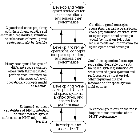
While this larger methodology is expressed in terms of a focus on space operations, it could be useful in all application areas for MNT. The methodology is based on a hierarchy of technical capabilities, system architectures, operational concepts, and grand strategies.
MNT will make dramatically improved systems possible, and it thus is important to develop and analyze system concepts using MNT [4]. Such systems must be evaluated in their operating context. MNT will so change the total environment of capabilities and actions, however, that it will transform the operating environment context for doing the analysis. This "chicken-and-egg" problem requires an iterative analysis methodology to resolve.
Figure 2 describes such an iterative process, built around the hierarchy of technical capabilities, system architectures, operational concepts, and grand strategies. Each level provides building blocks for assembling concepts at the level above. Thus, one can think synthetically, combining building blocks into concepts at the next higher level. Also, one can think holistically, using an intuition or theory about what MNT can achieve at a particular level to develop a concept at that level. In this latter case, one must then do a top down analysis to make sure that the lower levels can actually support this new concept, resulting in either a refutation or added confidence in the concept. Another result of this top-down analysis likely to be additions to the menu of building blocks at the levels below.
A first step in this methodology is to take a broad range of previously defined system architectures, and apply the Technical Performance Parameters of MNT to those architectures. This will provide an initial set of MNT-based system architectures from which to launch further analysis. Such system architectures are likely to be unbalanced, however, and thus will probably perform significantly less well than system architectures designed to exploit the particular capabilities of MNT. The research is this paper is part of that first step.
The primary means of taking advantage of MNT without changing these architectures is to use diamondoid materials with much higher strength-to-density ratios. This will reduce the mass of the vehicles' fuselages, wings and tails, undercarriages, and propulsion systems, roughly in proportion to the relative strength-to-density of diamondoid to the materials used. (Many parts of the propulsion system, however, would require appropriately coated surfaces, and external surfaces will require thermal protection for re-entry.) This research assumes that the systems were all be built of titanium in the original paper. The nature of the "on-board equipment" is not clear described in [5]. It probably includes mass for life support for pilots of the vehicles. Since the exact nature of this mass is unclear, the conservative assumption made here is that this mass could not be reduced at all with the use of MNT.
By flying the same trajectories, the mass savings from applying MNT to the vehicle's structure can be applied to the payload. This occurs directly for the SSTO vehicles and the second stages of the TSTO vehicles. Mass savings on the first stage of the TSTO vehicles are added proportionately to all components of those vehicles second stages, including the payload.
The resulting vehicle and payload masses, and mass ratios, are shown in table 3 below. The "Titanium" based numbers (first entry) are from [5]. The "Diamondoid" based numbers are assuming MNT materials. These results are consistent with [6], which describes an MNT-based SSTO with a payload to GLOW ratio of 1/6 and a ratio of payload mass to dry, empty vehicle mass of ~8.
| Architecture Titanium/ Diamondoid | "Dry, Empty Vehicle Mass" | Payload Mass | Mass Ratio | "Payload to Dry, Empty Mass Ratio" | Cost per kg to Reference orbit |
|---|---|---|---|---|---|
| 1) SSTO(H) | 92.5 / 16.5 | -32 / 44 | -6.4% / 8.79% | -35% / 267% | NA / $5.19 / $375 |
| 2) SSTO-SL | 57.3 / 10.5 | 9.8 / 56.6 | 1.96% / 11.33% | 17% / 541% | $29k / $3.91 / $185 |
| 3) SSTO-AL | 54.3 / 9.5 | 17.0 / 61.8 | 3.40% / 12.36% | 31% / 653% | $16k / $3.54 / $153 |
| 4) SSTO(V) | 57.4 / 9.4 | 4.8 / 52.5 | 0.96% / 10.50% | 8% / 540% | $59k / $4.26 / $185 |
| 5) TSTO(H) | 107.8 / 20.4 | 17.0 / 49.5 | 3.40% / 9.90% | 16% / 243% | $31k / $4.55 / $412 |
| 6) TSTO(V) | 70.4 / 14.5 | 25.0 / 53.5 | 5.00% / 10.70% | 36% / 368% | $14k / $4.17 / $272 |
The costs for the titanium systems were not in [5], but are based on a very simple minded per mission cost estimate of $1000 per kg of dry, empty launch vehicle mass, averaged over the life of the program. This may be extremely optimistic; using traditional aerospace approaches it would require a tremendous number of fleet missions conducted with low overhead. The cost for the diamondoid, MNT-based systems is based on the high end of the MNT manufacturing cost estimate from [1], applied to producing the vehicle and the fuel mass, and assuming the vehicle is used once. The third cost entry applies the per mission cost estimate of $1000 per kg of dry, empty launch vehicle mass to the diamondoid system masses.
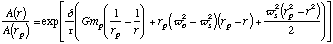
Skyhooks are generally much too long to support themselves if they are of constant thickness. The answer is to use cables tapered with the load so that they experience constant stress over their length. The ratio of the area of a skyhook at distance r from the planet to the area of the skyhook tip at the surface of the planet is expressed in equation (5) from [8]:
 (1)
(1)
Where A(r) is the area of the skyhook at radius r from the planet's center, A(rp) is the area of the skyhook at the planet's radius, rp is the planet's radius, d is the skyhook material's density, t is the tensile strength, wo is the orbital rate of the satellite, and ws is the rotation rate of the satellite. For a synchronous skyhook, ws = wo = wp (where wp is the planet's rotational rate). One particularly favorable concept is for a rotating skyhook roughly 1/3 the radius of the planet. This can be designed to make its closest approaches near exactly six stable points on the surface. It is also close to the optimum rotating skyhook length.
One measure of skyhook feasibility is the taper ratio, the ratio between the widest point in the skyhook and the tips. The taper ratio is proportionate to the exponent of the density to tensile strength ratio. [8] derived taper ratios, assuming graphite crystals and a substantial safety factor. Properly scaling those taper ratios based on the material properties achievable with MNT, gives improved feasibility, as shown on table 4 below.
| Body | Taper Ratio for Synchronous Using Graphite | Taper Ratio for Synchronous Using MNT | Taper Ratio for 1/3 Planet Radius Using Graphite | Taper Ratio for 1/3 Planet Radius Using MNT |
|---|---|---|---|---|
| Mercury | 2.22 | 1.71 | 1.42 | 1.27 |
| Venus | 123 | 25.2 | 8.32 | 4.13 |
| Earth | 100 | 21.9 | 10.1 | 4.69 |
| Moon | 1.3 | 1.19 | 1.12 | 1.08 |
| Mars | 2.41 | 1.8 | 1.56 | 1.35 |
| Jupiter | 2.8 x 10^26 | 5.3 x 10^17 | 7.0 x 10^15 | 4.1 x 10^10 |
| Saturn | 3.3 x 10^6 | 2.3 x 10^4 | 17,430 | 695 |
| Uranus | 2,350 | 182 | 101 | 22.1 |
| Neptune | 1 x 10^6 | 1 x 10^4 | 1,092 | 168 |
The ion engine discussed in [6] uses solar collectors with specific power on the order of nearly 105 W/kg to drive ion engines with a ~250,000 m/s ideal exhaust velocity, providing ~0.8 m/s2 acceleration. [2], suggests the specific power could be more than an order of magnitude greater, and a 1,000,000 m/s ideal exhaust velocity vehicle could provide ~9.8 m/s2 acceleration.
 (2)
(2)
Where R is the radius, g is the acceleration of pseudo-gravity at the rim, and G is the density. MNT offers a 5 x 10¹⁰ Pa tensile strength. Using the design rule of 50% safety factors for O'Neill style colonies [12], a 3.3 x 10¹⁰ Pa design tensile strength is reasonable. The associated material density is 3.51 103 kg/m3. One goal of the architecture is for g to equal 9.8 m/s2 [10],[12]. This all gives a possible space station radius of 9.6 x 10⁵ m, or nearly 1000 km. For comparison, the corresponding feasible radius for titanium is 14 km, and even at its ultimate tensile strength with no safety factor, the titanium limit would be 23 km.
At the 9.6 x 10⁵ m radius, the entire available strength (at the safety factor) of the MNT-based material is being used to prevent the rotating structure from bursting, and there is no strength left over to hold the space station's contents, including an atmosphere. To do so, a lower radius must be set.
The mass of an O'Neill style colony can be first approximated as the sum of mass of the structure, the mass of the furnishings, and the mass of the atmosphere. For the design sketched here, these sum to 1.6 x 10¹⁷ kg., or 1.6 x 10⁶ kg per person.
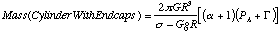 (3)
(3)
Where s is the design stress, PA is the internal atmospheric pressure, G is the additional load for other contents, and a is the length to radius ratio of the cylinder. A typical a, used here, is 10. [12] derives a requirement for 50.8 kPa internal atmosphere, and use a G equal to 16% PA. Since the total area of the structure is:
 (4)
(4)
One can directly solve for the structure radius where the shell is 5000 kg/m2. Using MNT materials, the structure will be 461 km in radius. For comparison, the equivalent number for titanium is 6.6 km, or for a titanium shell is at its ultimate tensile strength with no safety factor, 11 km.
A 461 km radius cylinder with endcaps, with a 4610 km long cylinder portion, has a surface area on that cylinder portion of 1.22 x 10¹² m2., half of which would be available for habitation (the other half being taken up with windows). The [12] requirement of 87 m2 land area per person (including land for agriculture) yields a possible population for this structure of 76 billion people. The stressed shell masses 8.0 x 10¹⁶ kg of carbon.
 (5)
(5)
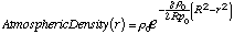
where r is any radius of interest within the cylinder, r0 is the atmospheric density at the outer radius, and p0 is the atmospheric pressure at the outer radius. Integrating along r through the cylinder and spherical endcaps gives a total required mass of only 7.2 x 10¹⁶ kg, or roughly 3% of what would be required to fill the cylinder uniformly. Near 36 km above the surface, the atmosphere will fall to only 1% of the surface density. Thus, each square meter of surface requires a roughly comparable mass of atmosphere above it, whether that surface is in a very large open space station as described here, or on the surface of Earth with real gravity.
The two most obvious extensions of this work would be to analyze the performance of other previously defined space system architectures when using the technical performance parameters of MNT, and to take these system architectures, and refine them to better take advantage of the estimated capabilities MNT will offer.
Further extensions should include designing example missions using estimated MNT space system capabilities and designing novel missions and systems to particularly exploit the technical capabilities of MNT. The ultimate goal should be to develop foresight on future capabilities for space operations adequate to make appropriate plans in the context of a developing molecular nanotechnology.
[2] Drexler K E 1995 Prospects in Nanotechnology: Toward Molecular Manufacturing ed M Krummenacker, J Lewis (New York: John Wiley & Sons) xvii-xviii
[3] Drexler K E 1986 Engines of Creation: The Coming Era of Nanotechnology (New York: Doubleday
[4] McKendree T L 1993 Systems Engineering in the Workplace (Proc. Third Annual Symposium National Council on Systems Engineering) ed J E McAuley, W H McCumber (Seattle: NCOSE) 417-424
[5] Shkadov L M, Denisov V Y, Lazarev V V, Plokhikh V P, Buzuluk V I, Volodin S V, Chervonenko K A, Skipenko V V, 1995 Acta Astronautica 35 47-54
[6] Drexler K E 1992 J. Brit. Interplanet. Soc. 45 401-405
[7] Pearson J, 1975 Acta Astronautica 2 785-799
[8] Moravec H 1977 J. Astronautical Sci. 25 307-322
[9] O'Neill G K 1974a Nature, 250 636
[10] O'Neill G K 1974b Phys. Today, September 32-40
[11] O'Neill G K 1975 Science, 190 943-947
[12] Johnson R D, Holbrow C, 1977 Space Settlements: A Design Study NASA SP-413 (Washington D.C.: NASA)
[13] O'Neill G K 1976 The High Frontier (Princeton: Space Studies Institute Press)