![]()
Ralph C. Merkle
Xerox PARC
3333 Coyote Hill Road
Palo Alto, CA 94304
merkle@xerox.com
www.ralphmerkle.com
This paper is available on the web at http://www.zyvex.com/nanotech/hydroCarbonMetabolism.html. It was published in Nanotechnology 8 (1997) pages 149-162. The published version may differ in some respects from this web page.
The author gave a talk based on this paper at the Fifth Foresight Conference on Molecular Nanotechnology.
If "103" is the same as "103" then your browser does not support superscripts and will mangle exponents.
A complete analysis of the reactions by which an assembler converts incoming raw materials into reactive tools used to synthesize molecular structures is greatly simplified if we restrict ourselves to the elements hydrogen and carbon, and further restrict our attention to structures that are relatively stiff (excluding, for example, floppy polymers). The stiff hydrocarbons include a wide enough class of materials to be a very attractive goal (diamond, graphite, and structurally related materials are included in this class). Essentially all mechanical structures can be made from stiff hydrocarbons; including struts, bearings, gears, levers, etc. This can be most readily seen by noting that the strength-to-weight ratio of diamond is over 50 times that of steel or aluminium alloys -- a single part made of metal could be functionally replaced by a similarly shaped stiff hydrocarbon part. The resulting part would be lighter and stronger than the part it replaced, improving overall performance. The class of stiff hydrocarbons also includes molecular computers which, by today's standards, would be extraordinarily powerful (Drexler, 1992).
A more general assembler, able to manufacture structures which incorporate most of the elements of the periodic table, would be substantially more difficult to analyze. One approach to breaking down the task of building a relatively large and complex structure would be to consider a series of small incremental changes to an exposed surface, the cumulative effect of which would be to manufacture the whole. This implies we must analyze small changes to the exposed surface, presumably by considering small clusters of atoms on that surface. A very minimal cluster might be a single atom and the atoms to which it is bonded. If one atom is bonded to (say) three neighbors, and all four atoms can be any one of about 100 possibilities, then this gives us 1004 or ~100,000,000 possible clusters. This analysis is crude and likely too small because (a) atoms are often bonded to more than three other atoms and (b) understanding an incremental change to a small cluster often requires examination of atoms farther away than one bond length. Despite its shortcomings, this crude model tells us that we will need to analyze many types of incremental surface modifications before we can reasonably hope to synthesize the full range of structures accessible using this approach.
By contrast, if our structures contain only hydrogen and carbon then the design and analysis problems become much simpler. Hydrogen can only be bonded to one other atom which, if we exclude hydrogen gas, must be carbon. A carbon atom will usually be bonded to two, three, or four neighboring atoms, which can only be hydrogen or carbon. Our previous crude analysis would assign 24 or 16 possible local clusters for carbon. While this can be reduced by considering isomers, it must also be increased to consider interactions that extend beyond a single bond length, e.g., aromatic rings and the like. In any event, the complexities of analyzing hydrocarbon structures with sufficient accuracy for the purposes discussed here is tractable with present capabilities. We cut short the combinatorial explosion before it begins.
While this rather drastic pruning makes the problems of designing and analyzing a hydrocarbon assembler more tractable, it does not directly address the feasibility of more general assemblers. Smalley in particular has argued (Smalley, 1997a) that a "completely universal" assembler is impossible, though he also said (Smalley, 1997b) "Most interesting structures that are at least substantial local minima on a potential energy surface can probably be made one way or another." He argues that a small set of molecular tools will be unable to catalyze all the reactions needed to synthesize the remarkably wide range of structures that are possible. Success will require the use of a great many custom-made catalytic structures.
Given the remarkable size of the combinatorial space of possible molecular structures it does indeed seem likely that at least some members of this space will resist direct synthesis by an assembler equipped with a relatively modest number of molecular tools. However, even if we assume that a substantial percentage of the space is inaccessible via this route (an assumption as yet lacking any clear support) the remaining "small" fraction would include structures of enormous value. Even the ability to manufacture only the highly restricted range of structures defined by the stiff hydrocarbons would usher in a revolution in manufacturing.
Further research aimed at clarifying the range of structures amenable to synthesis by positionally controlled molecular tools seems called for. Ideally, this would include not only the proposal and analysis of particular sets of molecular tools and the range of structures they could reasonably make, but also proposals of structures which could not be synthesized by the use of positionally controlled molecular tools.
One example of an "impossible" structure is a cubic meter of flawless diamond. Before it could be finished, background radiation would have introduced flaws. Drexler argued that it should be possible to define a structure which would be stable if complete but unstable when almost complete, a sort of molecular stone arch (Drexler, 1986, page 246). However, a specific, relatively small, stiff and stable structure that can reasonably be viewed as "impossible" to synthesize using positionally controlled tools has not yet been proposed. While it seems likely that at least some such structures must exist, our understanding of this issue would be greatly improved by specific examples.
An assembler operates in some external environment. While many environments are possible, we consider one specific environment in this paper: a feedstock solution made from the solvent acetone; butadiyne as a source of hydrogen and carbon; neon to support acoustic waves in the interior of the assembler while at the same time not reacting with the highly reactive molecular tools; and a "vitamin" which provides small amounts of elements such as silicon, tin, and one (or more) transition metals -- used basically for catalytic purposes.
Butadiyne (C4H2) seems attractive as a source of hydrogen and carbon for several reasons. The linear structure of butadiyne means that a simple tubular structure, such as a bucky tube, can serve as a suitable binding site to bind butadiyne from the feedstock solution (Merkle, 1997a). As bucky tubes are themselves made of hydrocarbons, a system which can synthesize most hydrocarbons should be able to synthesize the required binding sites. Second, as suggested by the following, relatively simple reactions can be used to convert butadiyne into useful molecular tools. Third, butadiyne has two carbons for every hydrogen. While it's difficult at present to make precise statements about the ratio of carbon to hydrogen in the structural elements of a hydrocarbon assembler, the presence of graphite and relatively thick diamond structures would make carbon significantly more common than hydrogen. As the present proposal uses a single molecule to provide both hydrogen and carbon, a molecule with a relatively high ratio of carbon to hydrogen is desirable (provided other constraints can be met).
By definition, an assembler can make another assembler: they are self replicating (Merkle, 1992, 1994, 1996a). To support self replication it is essential to achieve closure: it must be possible for the assembler to make everything it needs from the feedstock. In this paper, which focuses on the needed molecular tools, we must show that it is possible to generate a new set of molecular tools given only an existing set of molecular tools and a supply of butadiyne. It is not quite sufficient to show that it is possible to make each individual tool given the set of molecular tools and butadiyne. For example, if we could make one dimer deposition tool but used two hydrogen abstraction tools in the process, and we could make one hydrogen abstraction tool but required two dimer deposition tools in the process, then it would be impossible to make a new set of molecular tools from an existing set of molecular tools. The process would "run down hill" until we had exhausted our initial set of tools.
We will first consider how to make each molecular tool, and then consider "quantitative parts closure" in a later section to ensure that it is possible to manufacture a complete set of new tools without depleting an existing set.
(1) sigma2 = kT/ks
where:
Once we know how much positional uncertainty we can tolerate -- and for specific molecular tools that are used to cause specific reactions to occur at specific sites, we can compute the maximum positional uncertainty that can be tolerated before something goes wrong -- then we can design a positional device with the required stiffness. This can be done either by scaling the device size, or by specifying the operating temperature. If we specify room temperature operation then we find that the device size is largely dictated to us. (Drexler, 1992) analyzed this problem and concluded that a robotic arm of about 100 nm (nanometers) in height and 30 nm in diameter and made of diamondoid materials would have a positional uncertainty at room temperature that was a modest fraction of an atomic diameter. (Merkle, 1997b) reached substantially the same conclusions. Stiff hydrocarbons should suffice to make both these and many other positional devices.
To provide a numerical example: if a positional device has a stiffness ks of 10 N/m, then at room temperature (kT ~ 4 × 10-21 J) equation (1) implies a positional uncertainty sigma of 0.02 nm (0.2 Å). The gaussian fall off implies that positional errors of even a few sigma are of very low probability. A properly designed diamondoid positional device should easily be able to achieve a stiffness much higher than 10 N/m. For comparison, the carbon-carbon bond has a stretching stiffness of about 440 N/m.
Put another way, the energy of a system is:
(2) E = 1/2 ks x2
For our example ks of 10 N/m, a 0.154 nm (1.54 Å) deviation (about the length of a carbon-carbon bond) increases the energy of the system by 1.18 × 10⁻¹⁹ J (17 kcal/mol). Such a positional device is very unlikely to make an error as large as a bond length at room temperature.
The molecular tool itself cannot be scaled. A specific molecular tool operated at a particular temperature will have an upper bound on reliability that cannot be improved regardless of how stiff we make the supporting robotic arm. While the molecular tool cannot be scaled, it can be redesigned. The unmodified hydrogen abstraction tool has an estimated lateral stiffness at the carbon atom at its tip of about 6 N/m (Drexler, 1992, figure 8.2). (This tool is long and thin, which is adverse for stiffness). Drexler suggested buttressing the relatively flexible base of the hydrogen abstraction tool, and proposed one redesign which had an estimated stiffness of 65 N/m.
Ultimately, the room temperature reliability of molecular tools suitable for the synthesis of hydrocarbons depends on the achievable stiffness. Existing work suggests that reliable operation at room temperature can be achieved.
While butadiyne was selected here as the primary feedstock molecule, this choice was motivated by considerations involving the simplicity and ease of analysis of the reactions and the simplicity of the binding site. Other hydrocarbon feedstocks will likely be advantageous when other criteria are used (e.g., ease of bulk production and handling of the feedstock).
![]()
The elevation of the ethynyl radical to the status of "the" hydrogen abstraction tool is based on two main factors. First, it has a higher affinity than almost any other structure for hydrogen. While the H-F bond is stronger than the H-C bond in H-C#C-H, it is unclear how to hold and position a fluorine atom while retaining its high hydrogen affinity. Second, the ethynyl radical has desirable steric properties: it is unencumbered by bulky side groups and and can more easily abstract hydrogens from somewhat less accessible locations.
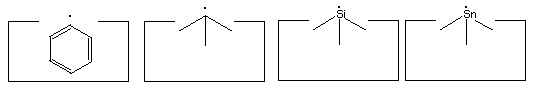
Many other radicals exist. The group IV radicals -- carbon, silicon, germanium, tin and lead -- seem particularly useful as they can be bonded to three supporting atoms in their radical state. This provides high stiffness and permits relatively large forces to be applied if desired. Group IV radicals also permit selection of radical properties -- the ethynyl radical is the strongest, the phenyl radical -- C6H5 -- is next, followed by the sp3 carbon radical; and then the silicon, germanium, tin and lead radicals in order. Radical properties can be fine tuned by modifying the supporting structures.
Many of the following reactions use one or more radicals. It is often unclear which radical would best serve a particular function. As a consequence, the specific radicals illustrated should be viewed as suggestions: substitution of alternative radicals, particularly other group IV radicals, might well prove advantageous.
Carbenes have proven remarkably useful in the synthesis of organic compounds. Positionally controlled carbenes should be equally if not more useful.
The ability to add two carbon atoms in a single operation using a dimer deposition tool provides more options in adding carbon to a growing structure. (A "dimer" is simply two of something joined together -- in this context, the "dimer" refers to two carbon atoms that are joined together by a triple bond: -C#C- ). While the addition of larger molecular fragments (e.g., polyyne strands, small segments of graphite, etc) will likely prove desirable in many circumstances, the short length of the present paper imposes limits on what we can consider. Future proposals will no doubt consider the advantages of adding larger moieties during the synthesis of hydrocarbons.
The remarkable utility of transition metal catalysts in chemical synthesis rather strongly suggests that positionally controlled transition metals can play a useful role in the synthesis of hydrocarbons. While the present paper uses only a single transition metal it seems likely that more than one will prove useful, particularly as we consider catalyzing a wider range of reactions than the specific ones considered here.
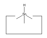
No single proposal is at present accepted as archetypal for the hydrogen deposition tool. Tin is a plausible candidate, as it forms a weak bond to hydrogen. Lead has an even weaker bond to hydrogen and so might prove superior.
We assume that synthesis takes place in an inert environment (vacuum or a noble gas) and that positional control is used throughout. (As the tools are often highly reactive, positional control is essential to prevent undesired reactions). These assumptions permit the use of novel and relatively simple reaction pathways. While the ability to achieve an inert environment using present methods might lead to an attractive implementation pathway, the primary point of the present discussion is to establish that, given a suitable environment, a relatively simple set of reactions and a relatively simple set of molecular tools should be sufficient to let us make the class of stiff hydrocarbons. This class of materials, with a few additions, should be sufficient to let us build some simple assemblers. This class would also let us build environments that would be inert, and in which reactive tools could be deployed with low error rates.
 A
bucky tube, such as the (9,0) bucky tube illustrated at
the right, could serve as a binding site for a simple
linear molecule like butadiyne (Merkle, 1997a).
Such a binding site would serve to bind the butadiyne
from the external feedstock solution, and would
allow the transfer of the bound butadiyne to the interior
of the assembler.
A
bucky tube, such as the (9,0) bucky tube illustrated at
the right, could serve as a binding site for a simple
linear molecule like butadiyne (Merkle, 1997a).
Such a binding site would serve to bind the butadiyne
from the external feedstock solution, and would
allow the transfer of the bound butadiyne to the interior
of the assembler.
Free molecules inside the assembler
must be avoided, as their uncontrolled collisions would
produce undesired and unpredictable reactions. It is therefore
most convenient to bond to butadiyne so that we can control
its position and prevent
it from uncontrolled encounters with, e.g., the reactive tools
discussed here. As there are initially no bonds to the butadiyne it must
be held in place by intermolecular forces (predominantly
van der Waals and
overlap repulsion forces) during the first bonding operation.
This paper does not consider in any detail the structure of the
site which both positions the butadiyne and makes it accessible
to the appropriate molecular tools for the initial bonding operation.
We do, however, point out that it
is possible to completely surround the butadiyne
with a custom-made structure specifically designed to position it
during this operation. We also point out that this site will in
general be very different from the binding site used to initially
bind butadiyne from the feedstock solution.
As there are several tools, there are several candidates for the initial reaction. A carbene could be inserted into any of the bonds. As there are six atoms and five bonds, the carbene could potentially be inserted into any of five positions. There are three positions that are fundamentally distinct: one of the H-C bonds, one of the C#C triple bonds, or the central C-C single bond. Perhaps the most attractive possibility would be to insert a carbene into the H-C bond exposed when the butadiyne first enters the internal environment from its binding site. If the binding site is a bucky tube, then as the butadiyne first exits the bucky tube it could be met with a carbene. A detailed examination of such geometries is necessary to ensure that (1) the carbene will insert into the H-C bond, (2) the carbene will not insert into the adjacent C#C triple bond (despite the attractive electron density provided by the pi bonds) and (3) the butadiyne won't "slip by" and permit bonding in some other (undesired) location or fail to bond at all.
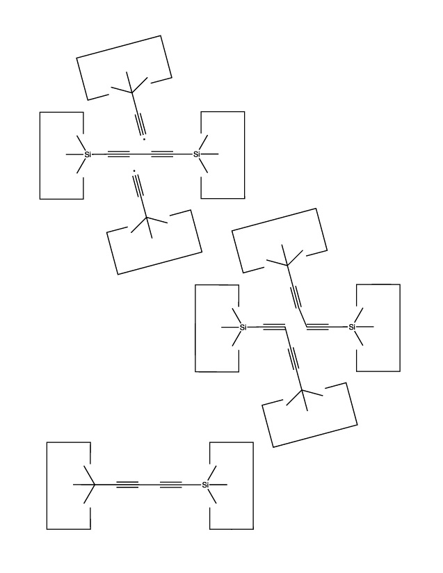
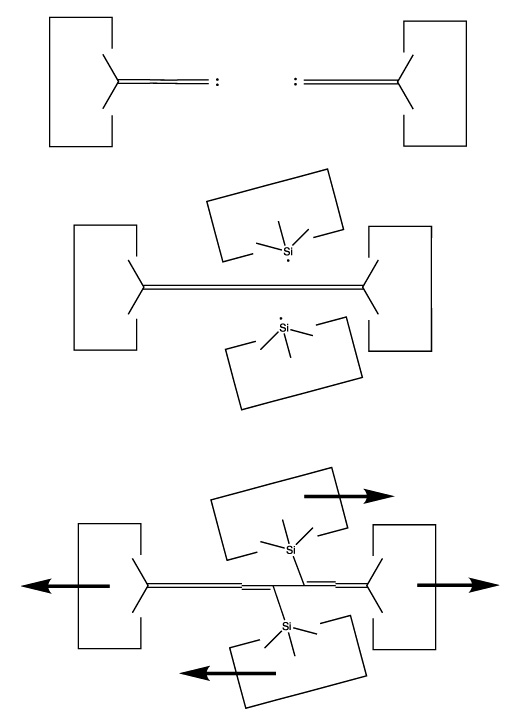
The use of radical additions might be a more attractive approach. As addition of a single radical would (a) permit the butadiyne considerable freedom (it could rotate around the newly formed bond) and (b) result in an open shelled (radical) structure, it would seem preferable to add to the butadiyne with two radicals and form two bonds to it. As we have several radicals to choose from and four carbons and two hydrogens as potential targets, there are many possible specific choices. One choice that seems particularly useful is two silicon radicals adding at the 1 and 4 positions. Following these additions the butadiyne moiety would be well controlled positionally, and we could remove the two hydrogens by applying two hydrogen abstraction tools. These reactions are illustrated below:
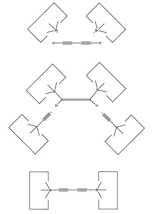
Calculations at the 6-311+G(2d,p) Becke3LYP // 6-31G* Becke3LYP level show a barrier height for the addition of a single silicon radical (SiH3) to a terminal carbon of the C4H2 of 14 × 10-21 J (~ 2 kcal/mol). The geometry was optimized at the lower level of theory while a single point calculation at the optimized geometry was computed using the higher level of theory. Calculations were done using the Gaussian B3LYP keyword without zero-point vibrational correction. Details are available on the web at http://www.zyvex.com/nanotech/comp/. The "transition state" was not actually a stationary point on the potential energy surface as rotations of the SiH3 moiety were blocked. (It is possible that the barrier to addition might be an artifact of this constraint). As the SiH3 is supposed to be the tip of a larger tool (which would hinder any rotations), this better models the expected application.
The computed barrier is about three times thermal noise at room temperature, suggesting that the actual barrier for this radical addition is in any event small, and therefore that this reaction will be satisfactory in the present application (especially as activation energy could if necessary be provided by the use of mechanical force).
The use of silicon radicals in this first step permits us to use hydrocarbon structures to confine the butadiyne with less concern that surface hydrogens will be abstracted: the silicon-hydrogen bond is weaker than the carbon-silicon bond. As the radical will have to approach the butadiyne quite closely during the radical addition, and as the hydrocarbon structure confining the butadiyne will also have to be in close proximity to the butadiyne, allowing close proximity between the silicon radical and the confining structure relaxes a significant design constraint.
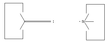
Another attractive possibility would be the use of two radicals but with different targets: one would attack a terminal hydrogen and the other would attack the adjacent carbon. If both radicals are appropriately positioned then this reaction could take place as the butadiyne emerged from a bucky tube. The result would be to transfer the hydrogen to one radical and the C4H to the other radical.
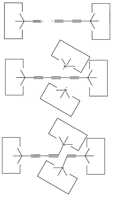
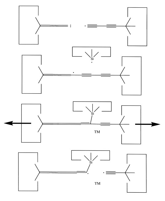
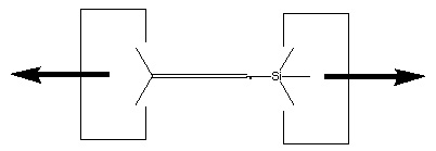
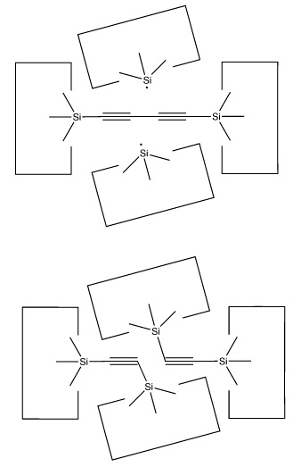
We will sometimes wish to transfer a single carbon atom from the end of one cumulene to another (rather than transferring a dimer consisting of two carbon atoms from a polyyne to a cumulene). Two cumulenes are joined, and then separated. The point of separation is different from the point where they were joined. The point of separation is controlled by the point at which two silicon radicals are applied to the cumulene strand. This is illustrated in the following sequence:
The obvious solution to both these problems is to transfer the hydrogen from the abstraction tool to the deposition tool.
As noted earlier, there are many possible structures that would serve as a hydrogen deposition tool. One candidate is tin, which forms a weak bond to hydrogen. One reaction to transfer a hydrogen from the abstraction tool to the depsosition tool is shown:
![]()
While this reaction is most useful, the tin radical is quite weak. While AM1 suggests that the H-C bond is weakened to 3 × 10-19 J (~45 kcal/mol) by the radical addition, there might still be a barrier to abstraction by tin (and the AM1 estimate might itself be seriously in error, see below). On the other hand, positional control can be used to weaken the H-C bond by, e.g., straightening the C#C-C angle; and can also be used to overcome any barrier by the use of an applied force. It will be necessary to examine this reaction more carefully to determine if transfer of the hydrogen to tin can be performed in one step. If not, the hydrogen could be transferred to a somewhat stronger radical as an intermediate step.
If there is an excess of carbon, then we could build carbon-rich structures. The obvious candidate is graphite. As the present paper is focused on the synthesis of the molecular tools and assumes that it is possible to make diamondoid structures (including graphite) from them, we will not investigate the reactions needed for the synthesis of graphite here.
If we deal with an excess of carbon by building carbon-rich structures and keeping them within the assembler, then we need not design mechanisms for ejecting waste from the assembler. This "zero residue" design is attractive because of its simplicity.
The second possibility is that we have too much hydrogen. In this case, we could build hydrogen-rich structures. Such structures would need to have a higher ratio of hydrogen to carbon than our feedstock molecule, C4H2. Even a 1:1 ratio would suffice, as in hydrogenated graphite. A more attractive structure is polyethylene, which has a ratio of two hydrogens for every carbon. As our feedstock has four carbons for every two hydrogens, one of the four carbons would have to be used in polyethylene to absorb the waste hydrogen (if we assume that no hydrogen at all was used in the actual structures being built). If our assembler was pure carbon (with no hydrogen at all) we would still be able to use three out of every four carbon atoms. As this seems unlikely, we should be able to use more than 75% of the carbon from the feedstock molecule if waste hydrogen is converted to polyethylene.
Strictly speaking, the use of polyethylene violates our stiffness constraint: polyethylene is floppy. The use of hydrogenated graphite does not violate this constraint and still provides a 1:1 ratio of hydrogen to carbon, which is sufficient. It seems likely, however, that many floppy structures can be synthesized with the tools proposed here, and that in many instances this will be convenient. The use of stiff diamondoid "jigs" to constrain the motion of otherwise floppy structures is one approach to their synthesis. Bonding to structures to constrain their motion is another approach. The end of a growing polymer chain could be held in a fixed position with respect to the next monomer to be added, as is done by the ribosome. As polymers are routinely synthesized today, it seems likely that methods for synthesizing them in an assembler are feasible. While convenient, such an ability is not necessary in an appropriately designed assembler, nor in a wide range of useful products that such an assembler could make.
Again, we assume that the synthesis of hydrogen-rich structures is feasible but do not analyze methods for synthesizing specific structures in this paper.
Another approach -- more efficient when large amounts of excess hydrogen are present -- would be to make large bucky balls and store the excess hydrogen inside them as H2 gas. Especially for large spherical bags the ratio of hydrogen stored to carbon used would be very high, as the amount of stored hydrogen would increase as the cube of the size of the bag, while the surface area (and hence the amount of carbon) would increase only as the square. This would eventually be limited by the strength of graphite (a sufficiently large bucky ball made of a single layer of graphite would eventually burst from the pressure) but bucky balls able to contain hydrogen at a pressure of perhaps 108 Pascals (~1,000 atmospheres) with a radius of some hundreds of nm should be feasible.
A third approach would be to generate hydrogen gas and pump it out of the assembler. This seems less desirable, as the hydrogen might reenter through the binding sites designed to bring larger molecules into the assembler. This would require more complex systems (such as the multi-stage cascade proposed by (Drexler, 1992)) to ensure that the interior of the assembler was not contaminated with any H2.
As the production of hydrogen gas inside the assembler cannot be allowed (for example, it would react with the hydrogen abstraction tool and other reactive structures that assume an inert environment) its production would have to be isolated in some fashion from the rest of the assembler. The production of hydrogen gas, although it has advantages, makes the system design more complex. The incorporation of hydrogen into hydrogen-rich structures seems like a simpler approach.
The most hydrogen-rich feedstock molecule is hydrogen gas. For various reasons (discussed earlier) hydrogen gas might not be desirable as a feedstock molecule. An alternative hydrogen-rich feedstock molecule would be methane, which has a sufficiently high ratio of hydrogen to carbon that it seems unlikely that useful hydrocarbon structures would have a higher ratio.
The most carbon-rich feedstock molecule of relatively small size would be some type of buckyball. C60 is the best known. Polyynes terminated by hydrogen are smaller and have a good hydrogen to carbon ratio, but become increasingly unstable as they are made longer.
For the present proposals, we will assume that the 2:1 ratio of carbon to hydrogen in butadiyne is approximately the same as the ratio of these elements in a hydrocarbon assembler. Any excess of either element will be dealt with by building hydrogen-rich or carbon-rich structures, as appropriate, and retaining these structures in the assembler (zero residue).
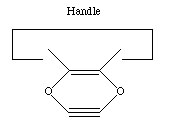
There are many possible dimer deposition tools -- the primary requirement is that the dimer be bonded relatively weakly to the rest of the tool so that after the dimer bonds to the desired target structure removal of the tool results in separation of the dimer from the tool. The general structure of a dimer deposition tool is illustrated below:
A more flexible approach would be to form two separately controlled weak bonds to the dimer, as illustrated below.
 A dimer deposition tool similar to a proposal by (Drexler, 1992),
is illustrated at the left.
This proposal
has the useful property that separation of
the dimer from its support causes a rearrangement of the bonding
structure, thus eliminating any dangling bonds in the tool
after the tool is withdrawn.
However, it is possible that this dimer will rearrange to the undesired
structure illustrated at the right.
This issue needs to be investigated further.
A dimer deposition tool similar to a proposal by (Drexler, 1992),
is illustrated at the left.
This proposal
has the useful property that separation of
the dimer from its support causes a rearrangement of the bonding
structure, thus eliminating any dangling bonds in the tool
after the tool is withdrawn.
However, it is possible that this dimer will rearrange to the undesired
structure illustrated at the right.
This issue needs to be investigated further.
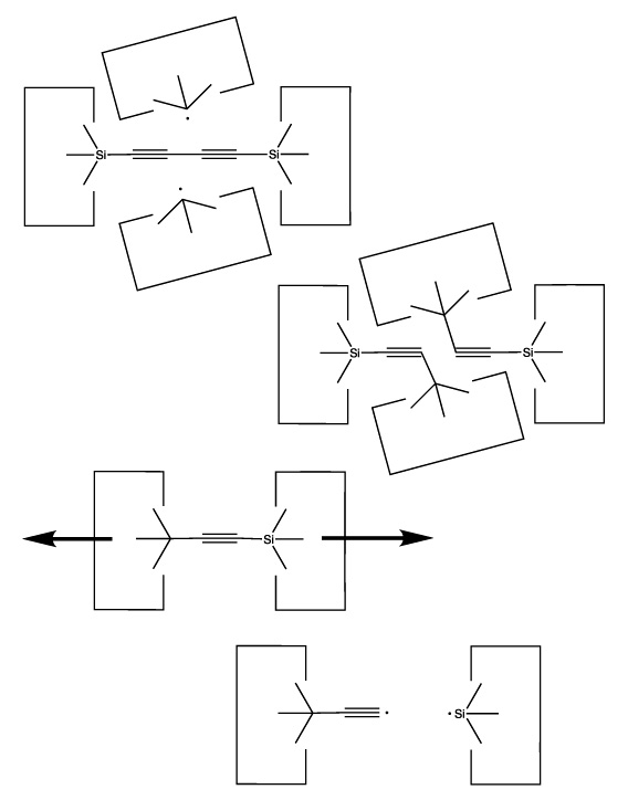
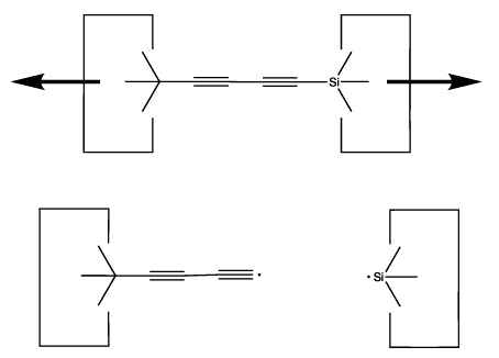
Once the dimer has been deposited on a surface and the tool withdrawn, the tool has been discharged and must be reloaded. Because dimer deposition tools are selected to bind weakly to the dimer (and hence to readily release the dimer when desired), reloading them is energetically unfavorable. In the following sequence we first split a four carbon polyyne chain (as provided by an earlier reaction) into two dimers, bonded at both ends to silicon. We then bend the Si-C#C-Si so that the reaction between it and the discharged dimer deposition tool is energetically favored. The two silicons are then rotated so that they are pointing at each other and force is applied until the approaching silicons form a Si-Si bond and break the Si-C bonds.
 Another proposal for
a dimer deposition tool is illustrated at the left. Ab initio calculations at the 6-31G* MP2 level using Gaussian (Frisch, 1995)
show all positive vibrational frequencies for the dimer deposition tool, thus
implying that it is stable in vacuum at a sufficiently low temperature. AM1
calculations show a barrier between this proposed dimer deposition tool and
the isomeric carbene (illustrated at the right) of about 4 × 10-19
J (~60 kcal/mol). Unfortunately, more accurate (and computationally intensive)
calculations at the 6-31G* Becke3LYP level show the barrier is only ~6 ×
10-20 J (~8 kcal/mol. This does not include zero-point correction),
almost an order of magnitude smaller. As a consequence, this dimer deposition
tool is unlikely to work reliably at room temperature.
Another proposal for
a dimer deposition tool is illustrated at the left. Ab initio calculations at the 6-31G* MP2 level using Gaussian (Frisch, 1995)
show all positive vibrational frequencies for the dimer deposition tool, thus
implying that it is stable in vacuum at a sufficiently low temperature. AM1
calculations show a barrier between this proposed dimer deposition tool and
the isomeric carbene (illustrated at the right) of about 4 × 10-19
J (~60 kcal/mol). Unfortunately, more accurate (and computationally intensive)
calculations at the 6-31G* Becke3LYP level show the barrier is only ~6 ×
10-20 J (~8 kcal/mol. This does not include zero-point correction),
almost an order of magnitude smaller. As a consequence, this dimer deposition
tool is unlikely to work reliably at room temperature.
While not all proposals for molecular tools will work as desired,
it is important to bear in mind that the computational methods used
to evaluate such tools can be made increasingly accurate by
increasing the computational effort devoted to the analysis.
Our confidence in the conclusions can be increased by
having more researchers analyze the problem with
multiple methods and greater computational power.
To start the analysis, we note that we can generate as many hydrogen abstraction tools (ethynl radicals) as desired. We start with a set of "spent" hydrogen abstraction tools (i.e., tools with a terminal hydrogen). We also require one functional hydrogen abstraction tool, one spent hydrogen deposition tool (the tin radical) and two silicon radicals. Using reaction 15, we transfer the hydrogen from the tip of the hydrogen abstraction tool to the hydrogen deposition tool. This consumes one hydrogen abstraction tool and one tin radical. We then use a reaction similar to reaction 8 to separate the two hydrogen abstraction tools. This produces two refreshed hydrogen abstraction tools, and leaves the two silicon radicals unchanged.
The net result of these reactions is to transfer a hydrogen from an abstraction tool to a deposition tool, while leaving the rest of the tool count unchanged. Of course, this reaction consumes a tin radical. As we are assuming that the hydrogen deposition tool will be discharged when we manufacture a structure which needs an additional hydrogen, and are further assuming that we can manufacture hydrogen rich structures if this is needed, we will not run out of tin radicals. Put another way, we can get rid of hydrogen by making hydrogen rich structures. When we do this, we remove hydrogens from hydrogen deposition tools. As these tools are simply hydrogen bonded to tin, removing the hydrogen creates tin radicals. This lets us produce as many tin radicals as might be desired.
As we can now refresh the hydrogen abstraction tool at will, we can freely use this tool in the manufacture of other tools. In particular, all other radicals can be generated from their hydrogenated precursors by applying the hydrogen abstraction tool.
Conversion of butadiyne into a bound polyyne (reaction 1 and 2) uses two hydrogen abstraction tools and two silicon radicals. Two additional silicon radicals are used in the production of two C#C dimers able to reload the dimer deposition tool (reaction 21). Loading of the dimer deposition tool results in the bonding together of two silicon radicals. However, these radicals can be regenerated simply by pulling them apart. As a consequence, the net effect of these reactions is to reload two dimer deposition tools with no net decrease in the number of silicon radicals. The two hydrogen abstraction tools used to remove the two hydrogens from butadiyne can be regenerated as discussed earlier.
Generation of carbenes from butadiyne uses only hydrogen abstraction tools, transition metals, and silicon radicals (reactions 9 through 14). The hydrogen abstraction tools are not limiting, and there is no net loss of silicon radicals in this process.
As a consequence, we can freely use all of these tools without concern that they cannot be refreshed. The manufacture of new hydrogen abstraction tools is shown in reactions 3 and 4, while creation of a new carbene insertion tool can be done by attaching a long cumulene to a diamond surface (such as the (100) surface) followed by severing the cumulene as in reactions 12 and 13.
We do not show the detailed synthesis of the positionally controlled transition metal(s), silicon radical or tin radical. As we now have an existing set of tools which we can freely use without concern that they will be irreversibly "used up," the synthesis of the other tools should be feasible. A detailed set of reactions for this process (which would require a specific proposal for the "vitamin" molecule) is needed, but is beyond the bounds of this paper.
This leaves us with a feedstock that consists of four main components:
We can view these four molecules as zero dimensional (neon), one dimensional (butadiyne), two dimensional (the 2-d tab on the vitamin), and three dimensional (acetone). This simplifies the interactions between the binding sites. Molecules of higher dimensionality cannot fit into binding sites of lower dimensionality, while molecules of lower dimensionality will have much lower affinity for binding sites of higher dimensionality. For example, almost nothing will fit into a snug binding site designed for neon. Impurities that can reasonably be expected to enter through a neon binding site are helium and H2. The former is harmless in small amounts, while the latter can be gettered from the external feedstock solution, thus insuring that the concentration of H2 in the feedstock solution is so small that it can be neglected.
In cases where a contaminant of lower dimension has a sufficient affinity for a binding site of higher dimension that it might be a problem, a specific method of eliminating the contaminant will be required. Most generally, the multi-staged cascade approach (Drexler, 1992) could be used. It is reasonable to expect that more special-purpose (and simpler) approaches will be sufficient for the present proposal (e.g., gettering of hydrogen).
Further research (including ab initio quantum chemical modeling and molecular dynamics) is required to establish that the particular reactions suggested here will work as desired. The more general conclusion is that the design of a complete set of reactions which can convert simple feedstock molecules into a desired set of molecular tools is feasible and should be pursued. Given the wide range of possible molecular tools, the wide range of molecular feedstock molecules, and the even wider range of possible chemical reactions for synthesizing tools from feedstock molecules, it seems certain that better proposals will be advanced.
 This
page is part of the
nanotechnology web site.
This
page is part of the
nanotechnology web site.